Lattice material with function gradients

A functional gradient and lattice technology, applied in building components, earthquake resistance, construction, etc., can solve problems such as high porosity, achieve excellent impact resistance, strong designability, and light weight of the structure

Active Publication Date: 2017-08-08
SOUTHEAST UNIV
View PDF4 Cites 23 Cited by
  • Summary
  • Abstract
  • Description
  • Claims
  • Application Information

AI Technical Summary

Problems solved by technology

[0002] With the rapid development of engineering technology, the excellent performance of functionally graded materials in improving surface contact damage has received extensive attention. Functionally graded materials change the spatial gradient of the microstructure so that the physical parameters of the material change in a gradient with the spatial position. The matrix material has high porosity, and the unit cell configuration design of the lattice str

Method used


Image

  • Lattice material with function gradients
  • Lattice material with function gradients
  • Lattice material with function gradients

Examples


Embodiment 1

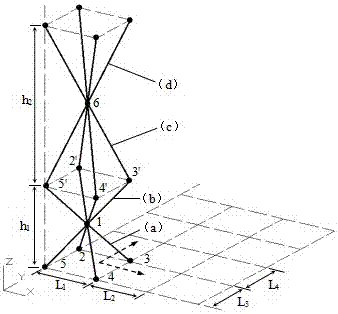
[0024] 1) if figure 1 As shown, this embodiment is a pyramid-shaped unit cell gradient function lattice material, which has a gradient function in the Z direction, and 1-6 is the endpoint of the pyramid-shaped unit cell rod, (a) is a pyramid-shaped unit cell , the endpoints on the bottom surface of the unit cell lie on the X-Y plane. The pyramid-shaped unit cell (a) is mirror-symmetrically extended and arranged with the X-Y plane where the vertex 1 is located as the symmetric plane to form the unit cell (b), and then the pyramid-shaped unit cell (c) is arranged with the X-Y plane where the vertex 6 is located. The plane is a symmetrical plane, and the mirror symmetrical extension arrangement is carried out to form a unit cell (d), and so on, to form a multi-layer spatial lattice structure, and the height of each layer is

[0025] 2) The unit cells are extended and arranged in the X and Y directions, and the distance between the end points on the bottom surface of the unit c...

Embodiment 2

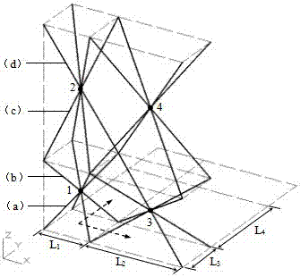
[0027] 1) if image 3 As shown, this embodiment is a pyramid-shaped unit cell gradient function lattice material, which has gradient functions in the X, Y, and Z directions. The mirror symmetrical continuation arrangement forms the unit cell (b), and then the pyramidal unit cell (c) takes the X-Y plane where the vertex 2 is located as the symmetry plane for mirror symmetric continuation arrangement to form the unit cell (d), with By analogy, a multi-layer spatial lattice structure is formed.

[0028] 2) The unit cells are extended and arranged in the X and Y directions, and the distance between the end points on the bottom surface of the unit cells changes during the extension process, that is, L 1 ≠ L 2 , L 3 ≠ L 4 , forming X, Y and Z direction functional gradient lattice materials.


PUM


Abstract

The invention discloses a lattice material with function gradients. The lattice material is formed through spatial expansion of a single cell element lattice structure. Single cell elements can be in a pyramid shape or in a tetrahedron shape or in other polyhedron shapes. The height direction of the single cell elements is the Z-axis direction. Dots on the bottom face of the single cell element are located on the X-Y plane. Single chip lattice structures are formed through extended arrangement of the single cell element structures in the X direction and the Y direction. During extended arrangement, the height of the single cell elements on the same layer in the Z direction are kept constant. The distances between upper endpoints of the bottom faces of every two adjacent single cell elements are not equal. The single chip lattice structure with different heights are subjected to mirror symmetry extended arrangement with the X-Y plane where the vertexes of the single cell elements located as the plane of symmetry, so that the multi-layer spatial lattice structure is formed. The physical property parameters of the lattice material represent gradient change along with spatial positions, the lattice material is low in dead load is low, high in designability and excellent in impact resistance, raw materials are easy to obtain, a manufacturing method is simple, and the application prospects are quite considerable.

Description

technical field [0001] The invention belongs to the technical field of engineering structures, and in particular relates to a lattice material with functional gradient. Background technique [0002] With the rapid development of engineering technology, the excellent performance of functionally graded materials in improving surface contact damage has received extensive attention. Functionally graded materials change the spatial gradient of the microstructure so that the physical parameters of the material change in a gradient with the spatial position. The matrix material has high porosity, and the unit cell configuration design of the lattice structure can make the lattice structure have the advantages of high specific strength, high specific stiffness, and high bending strength, so that a large amount of energy can be saved under the same structural bearing capacity. The material greatly reduces the weight of the structure, but the current research is mostly at the experime...

Claims


Application Information

Patent Timeline
IPC IPC(8): E04B1/19E04B1/98
CPCE04B1/19E04B1/98E04B2001/1978
Inventor 万水年玉泽沈孔健蒋正文宋爱明李夏元程宸周鹏
Owner SOUTHEAST UNIV
Why Eureka
Try Eureka