
Eureka
For R&D, Eureka makes reading and utilizing patents & technical documents easy.
Eureka AIR
Designed for self-driven R&D workflows. Generate viable solutions, solve complex R&D challenges, empower your innovation with AI.

Eureka Materials
Designed for material experts only. Revolutionize your material R&D, from search, analyze, to developing new materials.

TechResearch
Generate reliable direction feasibility study reports for your R&D in just a few steps.

TechSeek
Discover and master advanced knowledge NOW. Basics, ideas, possibilities, all at once.

TechMind
As an expert in R&D Theories, TechMind can generates customized viable solutions instantly.

TechRisk
Analyze your overall solution with one click, know your potential R&D risks in advance.

TechMonitor
Get weekly tech updates, stay abreast of the latest tech innovations and key insights.
Energy adjusting system
An energy adjustment, inertial body technology, applied in the direction of fluid transmission, belt/chain/gear, mechanical equipment, etc., can solve the problem of affecting system noise, vibration life and efficiency, unfavorable torque distribution of prime mover power shaft, affecting system pollution and emissions and other problems, to achieve the effect of simple structure, good environmental performance and good load response
- Summary
- Abstract
- Description
- Claims
- Application Information
AI Technical Summary
Problems solved by technology
Method used
Image

Examples
Embodiment 1
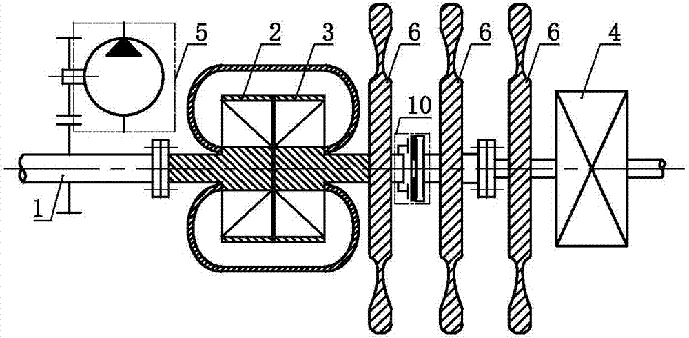
[0041] An energy regulation system such as Figure 1.1 and 1.2 As shown, it includes a power shaft 1, an impeller A 2, an impeller B 3, a transmission 4 and a hydraulic pump 5, the impeller A 2 and the impeller B 3 are connected in series, and the power shaft 1 and the impeller A 2 are transmitted Setting, the power shaft 1 is set in transmission with the hydraulic pump 5, the impeller B 3 is set in transmission with the transmission 4 through the clutch 10, on the impeller B 3, between the impeller B 3 and the transmission Inertia bodies 6 are arranged on the transmission parts between 4 and on the transmission parts of the speed changer 4 .
[0042] As a changeable implementation mode, in Embodiment 1 of the present invention, one or both of the transmission member between the impeller B 3 , the impeller B 3 and the transmission 4 and the transmission 4 can also be selectively selected. Inertia body 6 is set on each.
Embodiment 2
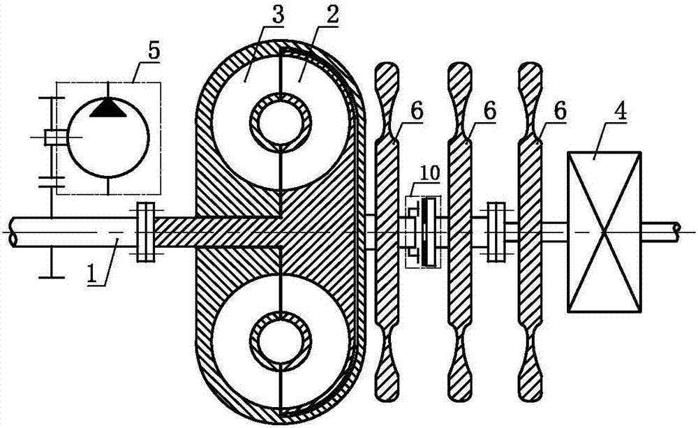
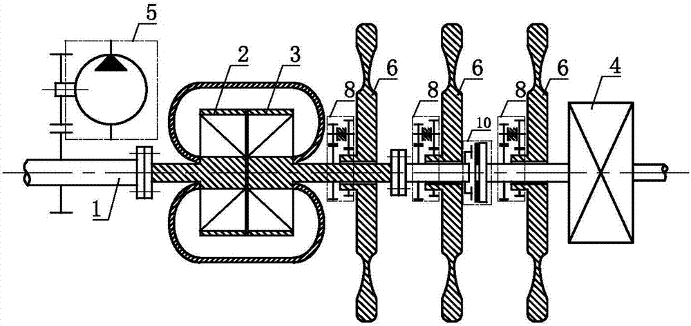
[0044] An energy regulation system such as figure 2 As shown, it includes a power shaft 1, an impeller A 2, an impeller B 3, a transmission 4 and a hydraulic pump 5, the impeller A 2 and the impeller B 3 are connected in series, and the power shaft 1 and the impeller A 2 are transmitted Setting, the power shaft 1 and the hydraulic pump 5 are set in transmission, the impeller B 3 is set in transmission with the transmission 4 through the clutch 10, and the impeller B 3, the impeller B 3 and the transmission 4 are connected The transmission member and the transmission member of the speed changer 4 are set through the speed increasing mechanism 8 and the inertia body 6 for transmission.
[0045] As a changeable implementation mode, in Embodiment 2 of the present invention, the impeller B 3 , the transmission member between the impeller B 3 and the transmission 4, and the transmission member of the transmission 4 can also be selected selectively. One or two pieces are set throug...
Embodiment 3
[0048] An energy regulation system such as Figure 3.1 and 3.2 As shown, including power shaft 1, impeller A 2, impeller B 3, impeller AB7, transmission 4 and hydraulic pump 5, the impeller A 2, the impeller B 3 and the impeller AB 7 are connected in series, and the power The shaft 1 and the impeller A 2 are set in transmission, the power shaft 1 is set in transmission with the hydraulic pump 5, the impeller B 3 is set in transmission with the transmission 4 through the clutch 10, and the impeller B 3 and the Inertia bodies 6 are arranged on the transmission elements between the transmissions 4 and on the transmission elements of the transmissions 4 .
[0049] As a changeable embodiment, Embodiment 3 of the present invention can also selectively choose to make the impeller B 3 , the transmission member between the impeller B 3 and the transmission 4 and the transmission member of the transmission 4 Inertia body 6 is set on one or two or three.
PUM
 Abstract
Description
Claims
Application Information
 - R&D Engineer
- R&D Manager
- IP Professional
- Industry Leading Data Capabilities
- Powerful AI technology
- Patent DNA Extraction
Browse by: Latest US Patents, China's latest patents, Technical Efficacy Thesaurus, Application Domain, Technology Topic, Popular Technical Reports.
© 2024 PatSnap. All rights reserved.Legal|Privacy policy|Modern Slavery Act Transparency Statement|Sitemap|About US| Contact US: help@patsnap.com