Closed type heat pump drying system with dehumidification function

A heat pump drying, closed-circuit technology, applied in drying, heat pump, dryer and other directions, can solve the problems of difficult temperature adjustment, low dehumidification energy consumption, slow drying rate, etc., to broaden the application field and improve the dehumidification energy. Consumption ratio, efficient drying effect

Active Publication Date: 2017-08-08
ZHONGYUAN ENGINEERING COLLEGE
View PDF6 Cites 11 Cited by
  • Summary
  • Abstract
  • Description
  • Claims
  • Application Information

AI Technical Summary

Problems solved by technology

[0003] The present invention provides a closed-circuit heat pump drying system with dehumidification function to solve the problem of serious environmental pollution, relatively low dehumidification energy consumption, Prominent technical problems such as high operating costs, slow drying rate, and difficult temperature adjustment

Method used


Image

  • Closed type heat pump drying system with dehumidification function
  • Closed type heat pump drying system with dehumidification function
  • Closed type heat pump drying system with dehumidification function

Examples


Embodiment 1

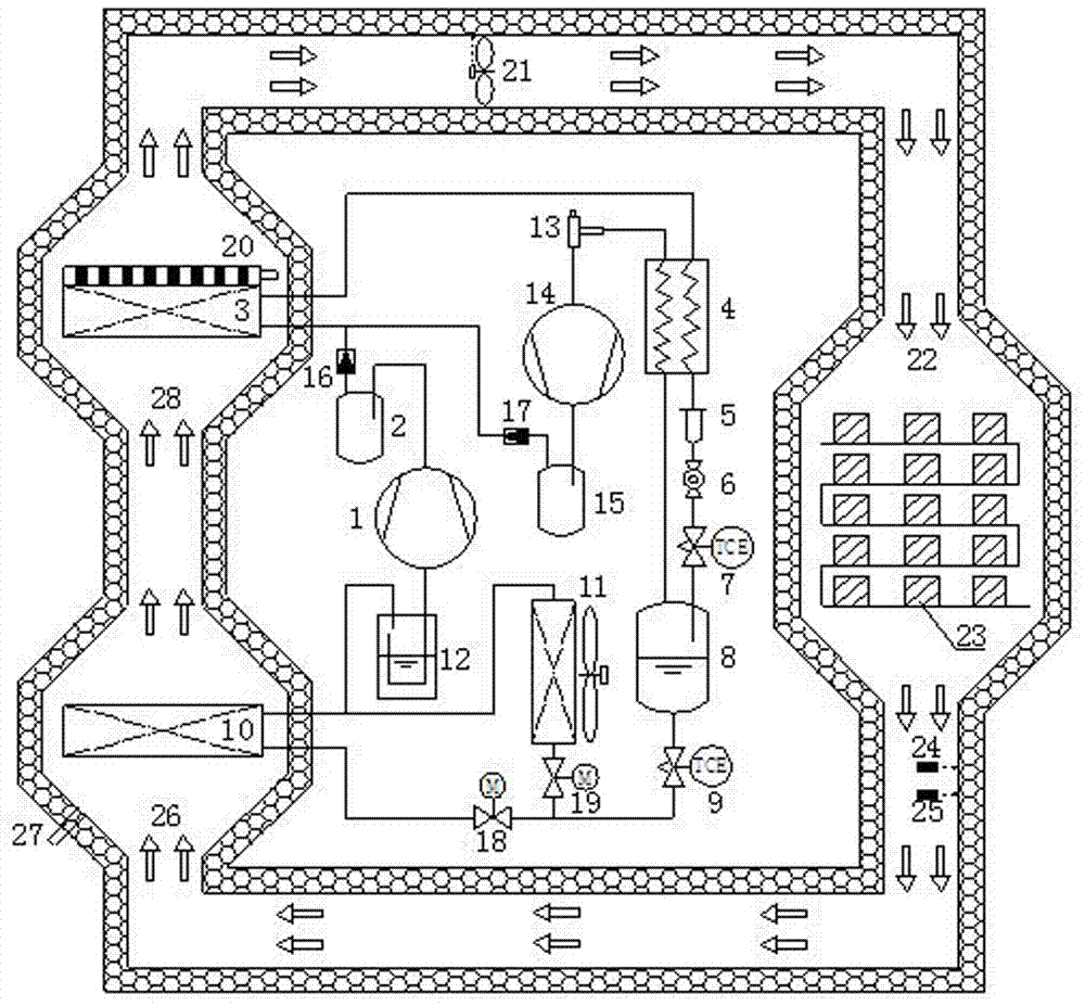
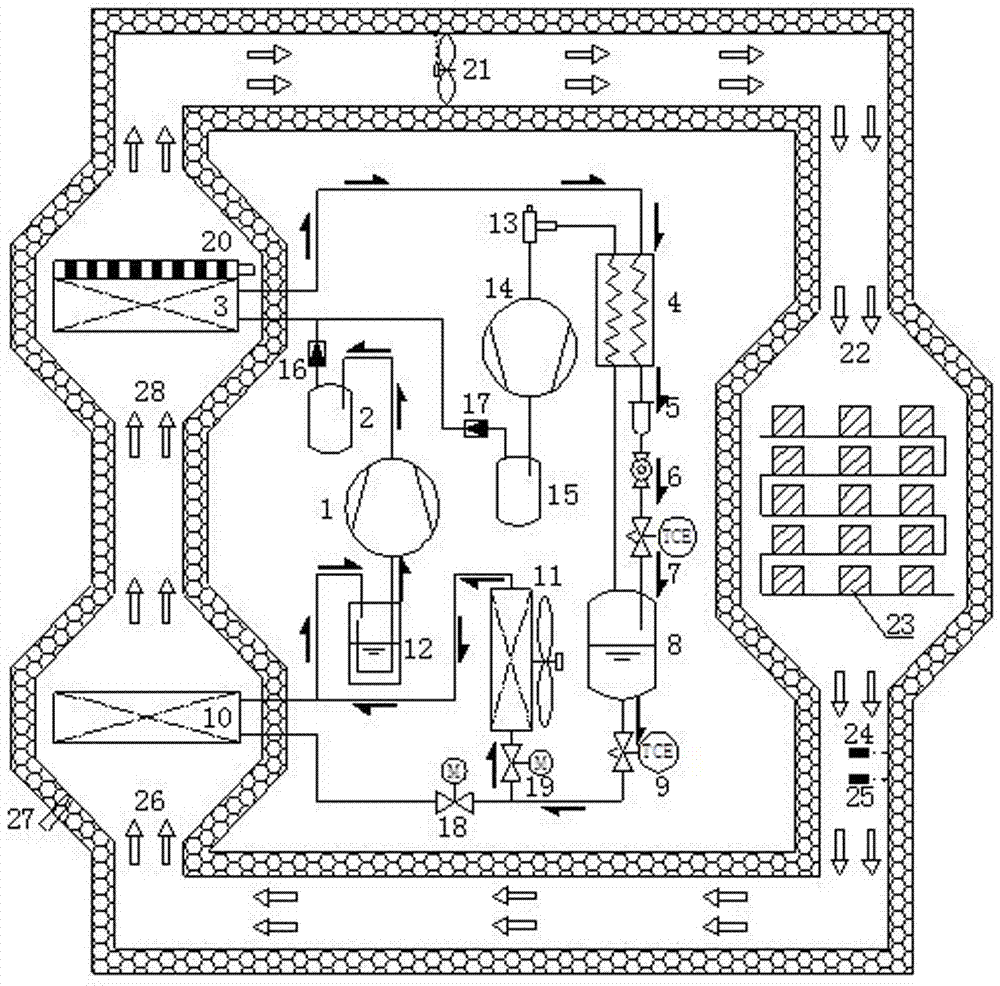
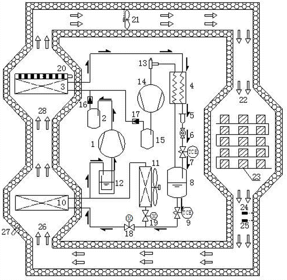
[0023] Such as figure 1 As shown, the present invention provides a closed-circuit heat pump drying system with dehumidification function, which is mainly composed of a three-pressure air-cooled heat pump subsystem and a closed-circuit drying medium circulation subsystem. The three-pressure air-cooled heat pump subsystem described therein consists of a main circuit compressor 1, a main circuit oil separator 2, a condenser 3, a recooler 4, a dry filter 5, an observation mirror 6, a first expansion valve 7, an intermediate Pressure gas-liquid separator 8, second expansion valve 9, dehumidification evaporator 10, heat source evaporator 11, low-pressure gas-liquid separator 12, evaporation pressure regulator 13, auxiliary circuit compressor 14, auxiliary circuit oil separator 15, first one-way Valve 16, second one-way valve 17, first electric regulator 18, second electric regulator 19 and connecting pipelines. Its specific connection relationship: the exhaust port of the main road...

Embodiment 2

[0026] The main circuit compressor 1 described in the present invention is a fixed-frequency rolling rotor compressor, and the auxiliary circuit compressor 14 is a variable frequency scroll compressor. The condenser 3 and the dehumidification evaporator 10 are stacked heat exchangers, and the heat source evaporator 11 is a parallel flow heat exchanger. The first expansion valve 7 is a manual expansion valve, and the second expansion valve 9 is a blocking expansion valve. The circulating fan 21 is a shifting fan. The evaporating pressure regulator 13 is a proportional regulator controlled by the pre-valve pressure (ie evaporating pressure). The recooler 4 is a flasher. Other structures are the same as in Embodiment 1.

Embodiment 3

[0028] The main circuit compressor 1 described in the present invention is a frequency conversion rolling rotor compressor, and the auxiliary circuit compressor 14 is a fixed frequency conversion scroll compressor. The condenser 3 is a stacked heat exchanger, the dehumidification evaporator 10 is a parallel flow heat exchanger, and the heat source evaporator 11 is a finned tube heat exchanger. The first expansion valve 7 is a thermal expansion valve, and the second expansion valve 9 is a flow-blocking expansion valve. The circulating fan 21 is a shifting fan. The evaporating pressure regulator 13 is a proportional-integral regulator. The subcooler 4 is any structural form of a plate heat exchanger, a casing heat exchanger, and a flasher. Other structures are the same as in Embodiment 1.


PUM


Abstract

The invention relates to the technical field of heat pump drying, in particular to a closed type heat pump drying system with a dehumidification function. The closed type heat pump drying system with a dehumidification function comprises a triaxial pressure air cooled heat pump subsystem and a closed type drying medium circulation subsystem, wherein the triaxial pressure air cooled heat pump subsystem comprises a main path compressor, a main path oil separator, a condenser, a subcooler, a drying filter, a medium-pressure gas-liquid separator, a dehumidification evaporator, a heat source evaporator, a low-pressure gas-liquid separator, an evaporation pressure adjusting valve, an auxiliary path compressor and an auxiliary path oil separator; the closed type drying medium circulation subsystem comprises an auxiliary PTC electric heater, a circulating fan, a drying material room, a material, a temperature sensor, a humidity sensor, a dehumidification chamber, a medium heating chamber and a connecting air flue. The closed type heat pump drying system solves the prominent technical problems that the existing drying technology is serious in environmental pollution, high in operating cost, low in drying speed and lower in dehumidification energy consumption, remarkably improves the efficiency that the heat pump dries the material, and ensures the color, quality and fragrance of the dried material.

Description

technical field [0001] The invention relates to the technical field of heat pump drying, in particular to a closed-circuit heat pump drying system with dehumidification function. Background technique [0002] Facing the increasingly prominent problems of energy shortage and environmental pollution, traditional drying technologies such as oil, gas, coal or wood have been gradually eliminated. There are currently two commonly used environmental protection drying technologies, one is to use electric heating The tube direct heating technology is easy to operate, but the efficiency is too low and the operating cost is high, which is contrary to the national energy-saving policy; the other is the heat pump drying technology, especially the air source heat pump technology, which is simple in structure, easy to install and use, and energy-saving. Environmental protection, some enterprises have begun to put it into use. However, the current conventional air source heat pump drying t...

Claims


Application Information

Patent Timeline
Patent Type & Authority Applications(China)
IPC IPC(8): F25B30/02F25B49/02F26B21/00F26B21/02
CPCF25B30/02F25B49/02F26B21/003F26B21/02Y02P70/10
Inventor 崔四齐刘寅刘恩海马静董岁具孙伟丽张双林杨开开赵艳艳
Owner ZHONGYUAN ENGINEERING COLLEGE
Why Eureka
Try Eureka