MIMO radar transmission and reception joint optimization method under unknown clutter knowledge condition

A joint optimization, radar transceiver technology, applied in the field of signal processing, can solve problems such as performance degradation of MIMO radar systems

Inactive Publication Date: 2017-08-08
DALIAN UNIV
View PDF4 Cites 13 Cited by
  • Summary
  • Abstract
  • Description
  • Claims
  • Application Information

AI Technical Summary

Problems solved by technology

Therefore, the optimized waveform obtained by relying on these estimated values ​​is bound to be affected by the estimation error, resulting in the performance degradation of the MIMO radar system

Method used


Image

  • MIMO radar transmission and reception joint optimization method under unknown clutter knowledge condition
  • MIMO radar transmission and reception joint optimization method under unknown clutter knowledge condition
  • MIMO radar transmission and reception joint optimization method under unknown clutter knowledge condition

Examples


Embodiment Construction

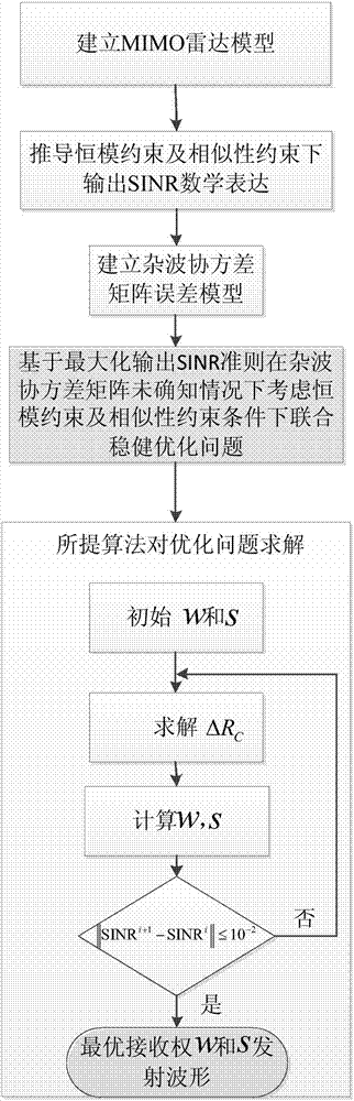
[0100] Attached below figure 1 The implementation steps of the present invention are further described in detail:

[0101] Based on the joint optimization method of MIMO radar transmission and reception under the condition of unknown clutter knowledge, it specifically includes the following steps:

[0102] (1) Establish MIMO radar model:

[0103] The MIMO radar is modeled as follows: the transceiver array is a uniform linear array, and the number of receiving array elements and transmitting array elements is N R and N T , the sending and receiving intervals are d R and d T , and are distributed in parallel, this arrangement makes the target have the same angle with respect to the receiving and transmitting array elements; assuming that the clutter can be modeled as a superposition of K clutter blocks, and the noise of each array element is a stationary white Gaussian noise, then in the case of a single pulse The received signal of is expressed as:

[0104]

[0105] Am...


PUM


Abstract

The invention belongs to the field of signal processing and in particular to a MIMO radar transmission and reception joint optimization method under an unknown clutter knowledge condition. The method comprises steps of: firstly establishing a MIMO radar model and deriving an output SINR mathematical expression under constant-modulus constraint and similarity constraint; then, establishing a clutter covariance matrix error model, and creating a joint robust optimization problem under the constant-modulus constraint and the similarity constraint under the unknown clutter prior information condition based on a maximum output SINR criterion; and finally, solving the optimization problem based on an iterative algorithm. Numerical simulation shows that the iterative algorithm can improve the robustness of MIMO radar detection obviously.

Description

technical field [0001] The invention belongs to the field of signal processing, and in particular relates to a combined optimization method for transmitting and receiving of MIMO radars under the condition of unknown clutter knowledge. Background technique [0002] In recent years, multiple-input multiple-output (MIMO) radar has attracted more and more researchers' attention due to its superior performance. Compared with traditional phased array radars, MIMO radars can use multiple transmitting elements to transmit almost arbitrary waveforms, the so-called waveform diversity. According to different antenna distances, it can be divided into distributed MIMO radar and centralized MIMO radar. Distributed MIMO radar transmits or receives with a large distance, so that targets can be detected from different angles, and then space diversity can be used to improve radar target detection performance. The distance between the receiving antennas of the centralized MIMO radar is rela...

Claims


Application Information

Patent Timeline
IPC IPC(8): G01S7/36G01S7/02
CPCG01S7/36G01S7/02
Inventor 王洪雁乔惠娇房云飞郑佳裴炳南
Owner DALIAN UNIV
Why Eureka
Try Eureka