Low-voltage winding structure of on-load capacitance regulation transformer, winding method of low-voltage winding structure and transformer

A low-voltage winding and transformer technology, applied in the direction of transformer/inductor coil/winding/connection, inductor/transformer/magnet manufacturing, transformer, etc., can solve the problems of high cost and can not effectively reduce space, etc. Withstand short-circuit ability and good manufacturability

Inactive Publication Date: 2017-08-08
SHANDONG ELECTRICAL ENG& EQUIP GRP INTELLIGENT ELECTRIC CO LTD +1
View PDF5 Cites 1 Cited by
  • Summary
  • Abstract
  • Description
  • Claims
  • Application Information

AI Technical Summary

Problems solved by technology

In this structure, each winding has two lead-out copper bars, and three windings lead out six lead-out copper bars, two of which are large-sectional area copper bars, and four are small-sectional area copper bars, and can be seen from the attached dr

Method used


Image

  • Low-voltage winding structure of on-load capacitance regulation transformer, winding method of low-voltage winding structure and transformer
  • Low-voltage winding structure of on-load capacitance regulation transformer, winding method of low-voltage winding structure and transformer
  • Low-voltage winding structure of on-load capacitance regulation transformer, winding method of low-voltage winding structure and transformer

Examples


Embodiment Construction

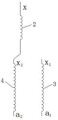
[0039] Such as figure 1 As shown, the low-voltage winding structure of the on-load capacity regulating transformer of the present invention is divided into three sections: the low-voltage I section 3 and the low-voltage II section 4 for serial parallel, and the low-voltage III section 2 for the common coil, the low-voltage III section and the Low pressure stage II pass x 2 connected together, and the other ends are independently led out.

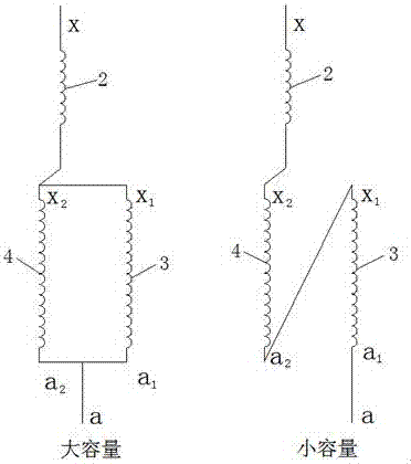
[0040] Such as image 3 and Figure 4 , Low-voltage III section 2, low-voltage I section 3 and low-voltage II section 4 are all made of copper foil, and copper bars are drawn out. The copper foil cross-sectional area and height of the low-voltage I section 3 and the low-voltage II section 4 are equal, and the copper foil cross-sectional area of ​​the low-voltage III section 2 is 1.9 to 2.2 times that of the low-voltage I section 3 or the low-voltage II section 4. . The copper foil height of low-voltage section III section 2 is equal to ...


PUM


Abstract

A low-voltage winding structure and winding method of an on-load capacity regulating transformer, and a transformer. The low-voltage winding structure includes a low-voltage section I, a low-voltage section II, a low-voltage section III, and five lead-out copper bars. The three sections are all wound with copper foil. The low-voltage section III is located on the inner side, and the low-pressure section I and the low-pressure section II are axially aligned and located on the outside; the low-voltage section III uses x copper bars and x 2 The copper bar is led out, and the low-voltage section I adopts a 1 Copper row and x 1 The copper bar is led out, and the low-voltage section II adopts a 2 Copper row and x 2 Copper row leads, copper row x 2 It is the co-arrangement of the low pressure III section and the low pressure II. The winding structure first winds the low-voltage section III, and the copper bars x and x 2 Lead out on the left side; then wind the low-voltage section II, and temporarily fasten the turns of the low-voltage section II after winding; then wind the low-voltage section I, copper bar a 1 、x 1 Lead out on the left; lead out copper bar a at the end 2 . The structure is made of copper foil, which has the characteristics of good manufacturability, high winding efficiency, high mechanical strength of the product, easy and tidy assembly of lead wires, etc., which improves the short-circuit resistance capacity of the transformer.

Description

technical field [0001] The invention relates to a structure and a winding method of a low-voltage winding of an on-load capacity regulating transformer and a transformer, which are applicable to oil-immersed and dry-type capacity regulating transformers and belong to the technical field of distribution transformers. Background technique [0002] The on-load capacity-adjusting transformer realizes the on-load capacity adjustment through the simultaneous conversion of high-voltage D-Y and low-voltage parallel-series. The low-voltage winding consists of three sections of turns, two of which are series and parallel turns, and one section is a common turn, with a total of six leads. At present, low-voltage windings mostly adopt a three-layer cylindrical structure, and the wires are composed of multiple radial and axial parallel paper-wrapped flat copper wires. Due to the radial direction and the number of windings, a standard transposition is required in the middle of each layer...

Claims


Application Information

Patent Timeline
IPC IPC(8): H01F27/28H01F27/29H01F29/04H01F41/061
CPCH01F27/2847H01F27/29H01F29/04H01F2027/2857
Inventor 孙业荣陈飞朱培珍张爱祥于安迎魏彩霞李西勋张松范云鹏宋士瞻王传勇韩蓬王坤代二刚张健康文文杨凤文王为帅孙彦硕李宇其侯文
Owner SHANDONG ELECTRICAL ENG& EQUIP GRP INTELLIGENT ELECTRIC CO LTD
Why Eureka
Try Eureka