Laminated lc filter

A kind of LC filter, stacked type technology, applied in the direction of stacked capacitors, inductors, fixed inductors, etc., can solve the problems of insufficient attenuation, inability to obtain high attenuation characteristics, etc., and achieve the effect of high attenuation characteristics

Active Publication Date: 2017-08-08
MURATA MFG CO LTD
View PDF12 Cites 4 Cited by
  • Summary
  • Abstract
  • Description
  • Claims
  • Application Information

AI Technical Summary

Problems solved by technology

[0056] However, in the multilayer LC filter 1100, after connecting the inductor L2 and the inductor L3 to each other, they are connected to the ground through the common inductor L23. Figure 9 As shown in , the attenuation pole near the passband, especially the attenuation pole on the high frequency side of the passband becomes insufficient attenuation, and high attenuation characteristics cannot be obtained

Method used


Image

  • Laminated lc filter
  • Laminated lc filter
  • Laminated lc filter

Examples


no. 1 approach

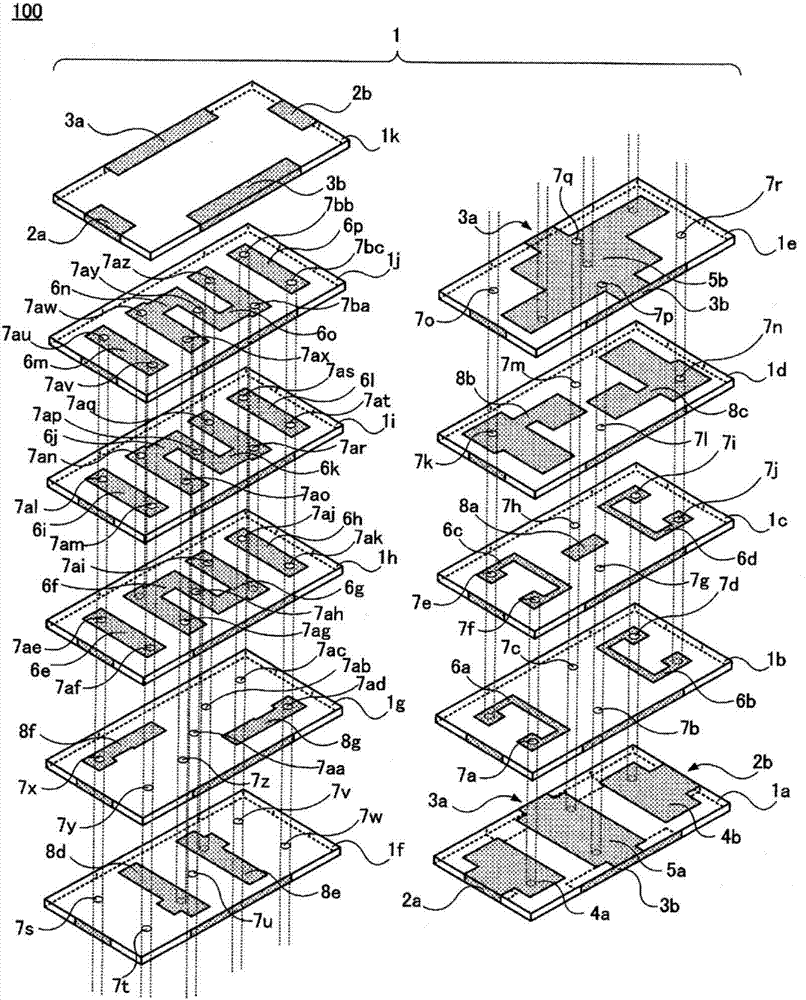
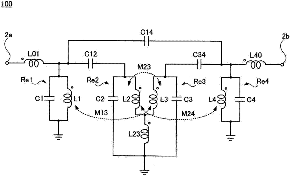
[0077] figure 1 as well as figure 2 The multilayer LC filter 100 according to the first embodiment is shown. in, figure 1 It is an exploded perspective view of the multilayer LC filter 100 . figure 2 is an equivalent circuit diagram of the multilayer LC filter 100 .

[0078] The multilayer LC filter 100 includes a multilayer body 1 in which eleven dielectric layers 1a to 1k are stacked in this order from the bottom. For the laminate 1 (dielectric layers 1a to 1k), ceramics are used, for example.

[0079] A pair of input / output terminals 2a, 2b are formed on opposing end surfaces of the dielectric layer 1a. In addition, ground terminals 3a, 3b are formed on the opposing side surfaces of the dielectric layer 1a.

[0080] In addition, connection electrodes 4 a and 4 b and a ground electrode 5 a are formed on the main surface above the dielectric layer 1 a. Furthermore, the connection electrode 4a is connected to the input / output terminal 2a, and the connection electrod...

no. 2 approach

[0165] Figure 4 A multilayer LC filter 200 according to the second embodiment is shown.

[0166] in, Figure 4 It is an exploded perspective view of main parts of the multilayer LC filter 200 . Also, for comparison, Figure 4 The multilayer LC filter 100 according to the first embodiment is also shown in .

[0167] In the multilayer LC filter 200 , the via electrodes 7an, 7ar, 7aw, and 7ba are omitted from the multilayer LC filter 100 according to the first embodiment.

[0168] That is, in the multilayer LC filter 100, when the line electrode portion of the inductor L2 of the second-stage LC parallel resonator Re2 is multilayered into three layers of line electrodes 6f, 6j, and 6n, the line electrodes 6f, 6j, and 6n are multilayered. 6j and 6n are connected to one end by via-hole electrodes 7ao and 7ax, connected to the middle parts by via-hole electrodes 7an and 7aw, and connected to the other ends by via-hole electrodes 7ap and 7ay. However, in the multilayer LC filter ...

no. 3 approach

[0172] Figure 5 A multilayer LC filter 300 according to the third embodiment is shown.

[0173] in, Figure 5 It is an exploded perspective view of main parts of the multilayer LC filter 300 . Also, for comparison, Figure 5 The multilayer LC filter 100 according to the first embodiment is also shown.

[0174] In the multilayer LC filter 300, like the multilayer LC filter 200 according to the second embodiment, the via electrodes 7an, 7ar, and 7aw are deleted from the multilayer LC filter 100 according to the first embodiment. , 7ba.

[0175] In addition, in the multilayer LC filter 300, the shape of the line electrodes 6f, 6j, and 6n of the line electrode portion of the inductor L2 constituting the second-stage LC parallel resonator Re2 is similar to that of the third-stage LC parallel resonator. The shape of the line electrodes 6g, 6k, and 6o of the line electrode portion of the inductor L3 of Re3 is changed.

[0176] Specifically, the two line electrodes 6f and 6g ar...


PUM


Abstract

The invention provides a laminated LC filter having wide passband and having an attenuation pole equipped with enough decrement surround the pass band. At least four LC parallel resonators (Re1-Re4) are provided inside a multilayer body. At least a pair of loops of inductors (L1,L3) in odd numbered-stage LC parallel resonators (Re1,Re3) among the at least four LC parallel resonators (Re1-Re4) are disposed at an angle at which magnetic coupling is obtained therebetween, and winding directions thereof are the same, so as to obtain magnetic coupling (m13) between the inductors (L1, L3). In addition, magnetic coupling (M24) may also be obtained between a pair of loops of inductors (L2,L4) in even numbered-staged LC parallel resonators among the at least four LC parallel resonators.

Description

technical field [0001] The present invention relates to a multilayer LC filter. More specifically, it relates to a multilayer LC filter having a wide passband and an attenuation pole having a sufficient amount of attenuation near the passband. Background technique [0002] As an LC filter suitable for miniaturization and light weight and having excellent characteristics, a multilayer LC filter is widely used. In this multilayer LC filter, a line electrode, a capacitor electrode, a ground The electrodes and the via electrodes form inductors and capacitors, and constitute the LC parallel resonator in multiple layers. [0003] In multilayer LC filters, it is required to have optimum frequency characteristics in accordance with the application. [0004] The above-mentioned laminated LC filter (laminated bandpass filter) is disclosed in Patent Document 1 (WO2012 / 077498). [0005] Figure 7 A multilayer LC filter 1100 disclosed in Patent Document 1 is shown. in, Figure 7 It is...

Claims


Application Information

Patent Timeline
IPC IPC(8): H03H7/09
CPCH03H7/09H01F17/0013H01F2017/0026H01G4/012H01G4/30H03H7/0115H03H2001/0085H01G4/40H01F27/2804H01F27/29H01F2027/2809H03H1/00H01G4/12H01G4/228
Inventor 今村光利
Owner MURATA MFG CO LTD
Why Eureka
Try Eureka