Safety remote-control ignition rod

A safe, ignition rod technology, applied in thermite welding equipment, welding equipment, metal processing equipment, etc., can solve the problem of operator's hand injury, etc., and achieve the effect of simple structure and simplified operation process

Inactive Publication Date: 2017-08-11
GELIN ELECTRICAL EQUIP PLANT WUXI CITY
View PDF6 Cites 7 Cited by
  • Summary
  • Abstract
  • Description
  • Claims
  • Application Information

AI Technical Summary

Problems solved by technology

However, the hand of the operating technician is less than 8cm away from the mold mouth. If t

Method used


Image

  • Safety remote-control ignition rod
  • Safety remote-control ignition rod
  • Safety remote-control ignition rod

Examples


Embodiment 1

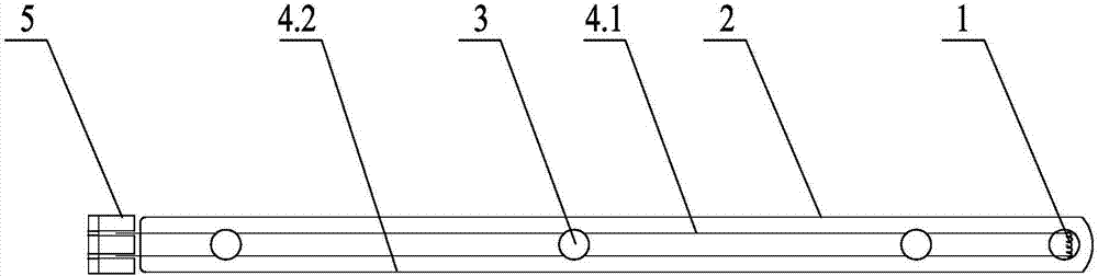
[0018] Such as figure 1 As shown, the safety-type remote control ignition rod includes a resistance wire 1, an introduction pipe 2, an insulating block 3, a first wire 4.1, a second wire 4.2 and a connector 5; inside the introduction pipe 2 along its length direction A first wire 4.1 and a second wire 4.2 are installed, the right end of the first wire 4.1 is connected to the right end of the second wire 4.2 through a resistance wire 1, and an insulating block 3 is arranged between the first wire 4.1 and the second wire 4.2 A socket 5 is provided on the left side of the left end of the introduction tube 2, and the left end of the first lead 4.1 and the left end of the second lead 4.2 are inserted into the socket 5.

[0019] When in use, after the graphite mold 8, the thermite flux 7 and the workpiece 9 to be welded are combined, the safety type remote control ignition rod of embodiment 1 is inserted into the reserved hole 10 on the graphite mold 8, and the lead wire 11 is conne...

Embodiment 2

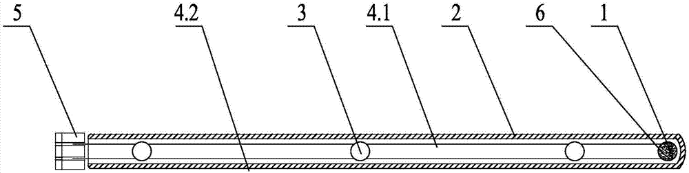
[0021] Such as figure 2 As shown, the safety-type remote control ignition rod includes a resistance wire 1, an introduction pipe 2, an insulating block 3, a first wire 4.1, a second wire 4.2 and a connector 5; inside the introduction pipe 2 along its length direction A first wire 4.1 and a second wire 4.2 are installed, the right end of the first wire 4.1 is connected to the right end of the second wire 4.2 through a resistance wire 1, and an insulating block 3 is arranged between the first wire 4.1 and the second wire 4.2 , on the left side of the left end of the introduction pipe 2 is provided with a socket 5, the left end of the first lead 4.1 and the left end of the second lead 4.2 are inserted into the socket 5; also includes a solid pilot fuel 6, a solid pilot fuel 6 Wrap the resistance wire 1 as a whole.

[0022] When in use, after the graphite mold 8, the thermite flux 7 and the workpiece 9 to be welded are combined, the safety type remote control ignition rod of emb...


PUM


Abstract

The invention relates to a safety remote-control ignition rod, in particular to a safety appliance which is used for ensuring the body security of operation technicists during metal welding by use of an exothermic welding flux, and belongs to the technical field of welding. The safety remote-control ignition rod comprises a resistance wire, a guide-in pipe, insulating blocks, a first wire, a second wire and a plug connector, wherein the first wire and the second wire are mounted in the guide-in pipe in the length direction; the right end part of the first wire is connected with the right end part of the second wire through the resistance wire; the insulating blocks are arranged between the first wire and the second wire; the plug connector is arranged on the left side of the left end part of the guide-in pipe; and the left end part of the first wire and the left end part of the second wire are inserted into the plug connector. The safety remote-control ignition rod is simple, safe and reasonable in structure, takes the resistance wire as the main element, realizes 'direct' ignition, and ensures that the technicists are prevented from being injured by jetting during reaction of the exothermic welding flux; and hands of the technicists can be moved from 8 cm away from a die to a safe operation area 1-5 m away from the die.

Description

technical field [0001] The invention relates to a safety type remote control ignition rod, in particular to a safety appliance used for the thermite flux to ensure the personal safety of technicians when welding metal, and belongs to the field of welding technology. Background technique [0002] At the end of the nineteenth century, with the development of the smelting industry and the chemical industry, the thermite welding method using thermite as a heat source appeared. This technology has the characteristics of simple equipment, less investment, fast welding operation, good welding effect, no need for high-power power supply during welding, and easy welding operation. It is especially suitable for field construction operations. [0003] Over the past few decades, the aluminothermic welding technology has developed from the original seamless welding of rails to the welding of copper core cables and cables, the welding of copper core cables on cathodic protection and steel...

Claims


Application Information

Patent Timeline
IPC IPC(8): B23K23/00
CPCB23K23/00
Inventor 钱琦陈铭康徐龙伟钱根源俞自立
Owner GELIN ELECTRICAL EQUIP PLANT WUXI CITY
Why Eureka
Try Eureka