
Polishing device for intelligently machining workpieces with regular shapes

An intelligent processing and polishing device technology, which is applied in the direction of grinding/polishing safety device, workpiece feed movement control, grinding workpiece support, etc., can solve the problem of high labor intensity, metal dust, workpiece heating cannot be processed in time, and operator health As well as the adverse effects of environmental protection and other issues, to achieve the effect of avoiding loosening of the workpiece

Active Publication Date: 2017-08-11
温州神一轴业股份有限公司
View PDF6 Cites 6 Cited by
  • Summary
  • Abstract
  • Description
  • Claims
  • Application Information

AI Technical Summary

Problems solved by technology

[0003] For shaft parts, the general-purpose polishing equipment clamps the workpiece and drives the workpiece to rotate. The rotating polishing wheel cuts into the work radially to achieve the purpose of polishing. During the operation, the loading and clamping of the workpiece and the polishing of the polishing wheel Cut-in and exit are mainly manual operations, with high labor intensity and low production efficiency, which cannot meet the needs of modern production
[0004] For the processing of workpieces with different hardness or the requirements of processing technology, it is necessary to replace multiple devices to meet the processing requirements for processing the same workpiece. At the same time, the metal dust generated in the processing project and the heat generation of the workpiece cannot be dealt with in time, which is harmful to the health of operators and Environmental Protection Causes Adverse Effects

Method used


Image

  • Polishing device for intelligently machining workpieces with regular shapes
  • Polishing device for intelligently machining workpieces with regular shapes

Examples


Embodiment 1

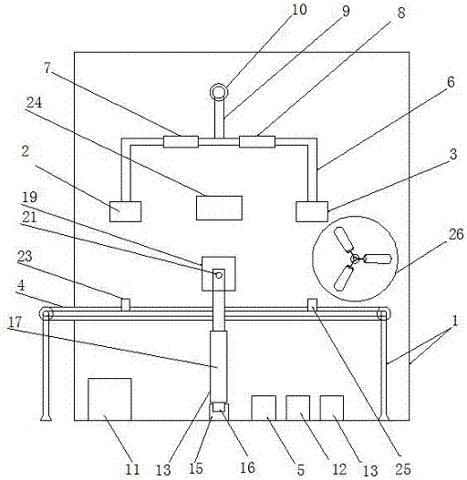
[0021] Such as figure 1 As shown, a polishing device for intelligently processing regular-shaped workpieces includes a frame 1, a first polishing wheel 2, a second polishing wheel 3, a conveyor belt 4 and a processor 5, wherein the first polishing wheel 2 And the second polishing wheel 3 is arranged at the position vertically above the frame 1, the first polishing wheel 2 and the second polishing wheel 3 are connected by a first connecting device 6, and the first connecting device 6 Including the first electro-hydraulic push rod 7 and the second electro-hydraulic push rod 8, the first electro-hydraulic push rod 7 and the second electro-hydraulic push rod 8 are connected to the processor 5, the first electro-hydraulic push rod 7 is used to control the horizontal movement of the first polishing wheel 2, the second electro-hydraulic push rod 8 is used to control the horizontal movement of the second polishing wheel 3, and the first connection device 6 is connected to the second c...

Embodiment 2

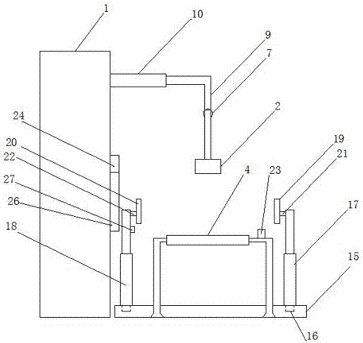
[0024] Such as figure 2 As shown, the material of the first polishing wheel 2 is set as soft sandpaper, and the material of the second polishing wheel 3 is set as hard sandpaper. The frame 1 is provided with a hardness tester 23 which is connected to the processor 5 and is used to test the hardness of the surface of the workpiece to be processed. The third connection device 10 is a hydraulic rod, and the hydraulic pump 11 drives the hydraulic rod to expand and contract.

[0025] Specifically, the operator places the workpiece to be processed on the conveyor belt 4, and the conveyor belt 4 transports the workpiece to be processed to the detection area of ​​the hardness tester. The first hardness interval and the second hardness interval are preset. The first hardness Any hardness value in the interval is greater than the hardness value in the second hardness interval, and the hardness detector 23 is used to detect the hardness value of the surface of the workpiece to be proce...

Embodiment 3

[0029] Such as figure 2 As shown, the frame 1 is also provided with a dust suction device 24 for absorbing metal dust generated during processing. The frame 1 is also provided with a temperature sensor 25, the temperature sensor 25 is an infrared temperature sensor connected with the processor 5 for detecting the surface temperature of the workpiece after processing. The frame 1 is also provided with a fan 26, which is connected to the processor 5 and used to cool the heated workpiece.

[0030] Specifically, the staff engaged in the polishing industry has been in contact with harmful metal dust for a long time, which is likely to cause occupational diseases such as pneumoconiosis. In the working area of ​​the second polishing wheel 3, when the first polishing wheel 2 or the second polishing wheel 3 are working, the dust suction device 24 is opened synchronously to absorb the harmful metal dust produced by the polishing of the polishing wheel in time, reducing the number of w...


PUM


Abstract

The invention discloses a polishing device for intelligently machining workpieces with regular shapes. The polishing device comprises a frame, a first polishing wheel, a second polishing wheel, a conveying belt and a processor; the first polishing wheel and the second polishing wheel are connected through a first connecting device; the first connecting device comprises a first electric-hydraulic push rod and a second electric-hydraulic push rod; the first electric-hydraulic push rod controls the first polishing wheel to horizontally move; the second electric-hydraulic push rod controls the second polishing wheel to horizontally move; the first connecting device is connected with a second connecting device; the second connecting device is connected with a third connecting device; the third connecting device is connected with the frame; and the conveying belt is arranged above the frame. The polishing device further comprises a hydraulic pump, a control device, a driving device, clamping devices and linear guide rails; the clamping devices are arranged on two sides of the frame; the linear guide rails are arranged below the frame; the clamping devices are connected with slide blocks to move in the linear guide rails back and forth; and the clamping devices include first hydraulic rods, second hydraulic rods, first clamping plates and second clamping plates.

Description

technical field [0001] The invention relates to the field of mechanical processing equipment, in particular to a polishing device for intelligently processing regular-shaped workpieces. Background technique [0002] Polishing equipment is a mechanical device that uses mechanical action to reduce the surface roughness of the workpiece to obtain a flat or smooth bright surface. Using polishing technology, the high-speed rotating polishing wheel forms extrusion and micro-cutting on the surface of the workpiece to remove microscopic unevenness on the surface. It can replace the traditional chemical surface treatment and avoid the possible pollution to the environment such as pickling necessary for chemical treatment. Actively promoting polishing technology is of great significance to environmental protection. [0003] For shaft parts, general-purpose polishing equipment clamps the workpiece and drives the workpiece to rotate. The rotating polishing wheel cuts into the work radi...

Claims


Application Information

Patent Timeline
Patent Type & Authority Applications(China)
IPC IPC(8): B24B29/02B24B27/00B24B49/00B24B41/06B24B55/06B24B49/14B24B55/02B24B49/12B24B41/00B24B41/02
CPCB24B27/0076B24B29/02B24B41/005B24B41/02B24B41/06B24B49/00B24B49/12B24B49/14B24B55/02B24B55/06
Inventor 蔡璟
Owner 温州神一轴业股份有限公司
Learn More