
Co-rotating differential multi-screw extruding machine with gradually changing type thread number and machining method thereof

A multi-screw extruder and gradient technology, applied in the field of twin-screw extruders, can solve the problems of weak stretching field, large and complex structure, high equipment cost, and achieve the effect of promoting interface renewal and expanding exhaust area. Effect

Inactive Publication Date: 2017-08-11
徐百平
View PDF0 Cites 4 Cited by
  • Summary
  • Abstract
  • Description
  • Claims
  • Application Information

AI Technical Summary

Problems solved by technology

This type of equipment mainly adopts building block structure to adapt to various material systems. The mixing effect is improved by adopting structures such as multi-thread structure and reinforced kneading block. However, the structure of the flow channel is symmetrical, and it is impossible to introduce tensile field strengthening. dispersion effect
In order to achieve high dispersibility, a large number of kneading blocks with wider disks are used, and high speed is used to increase the shear rate, which in turn brings about a decrease in the mixing effect caused by a decrease in the residence time, and a longer length of time has to be used. Diameter ratio to prolong residence time
Moreover, the use of a large number of kneading blocks destroys the axial conveying capacity and self-cleaning function, which leads to dry friction between the screws and makes it difficult to control the temperature, which brings many problems such as high energy consumption, low efficiency and material degradation.
Even so, it is not competent for the processing of material systems with high mixing requirements. In engineering, a two-stage combined structure of continuous banburying and co-rotating twin-screws is chosen. Although it meets some demanding processing requirements, there are problems such as very high equipment costs, There are both co-rotating twin-screw components and internal mixer components, which are difficult to operate and maintain, large and complex in structure, occupying a large area, and environmental pollution.
In recent years, with the in-depth study of chaotic mixing dynamics, the symmetry breaking effect and tensile force field have been introduced into the field of twin-screw technology, but there is still a lack of topological chaotic effect of channel segmentation, and the effect of the tensile field generated by forced compression is weak. There is still a lot of room for improvement in the melt blending and venting functions of the twin-screw extrusion process

Method used


Image

  • Co-rotating differential multi-screw extruding machine with gradually changing type thread number and machining method thereof
  • Co-rotating differential multi-screw extruding machine with gradually changing type thread number and machining method thereof
  • Co-rotating differential multi-screw extruding machine with gradually changing type thread number and machining method thereof

Examples


Embodiment 1

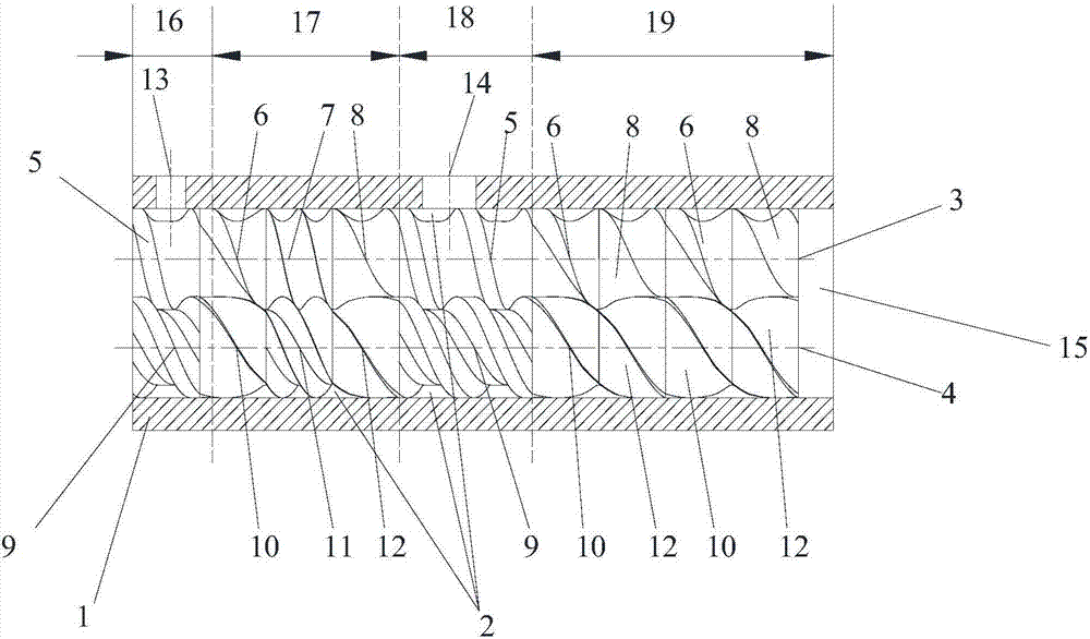
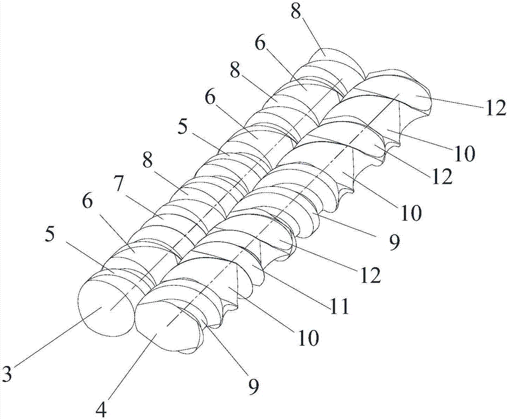
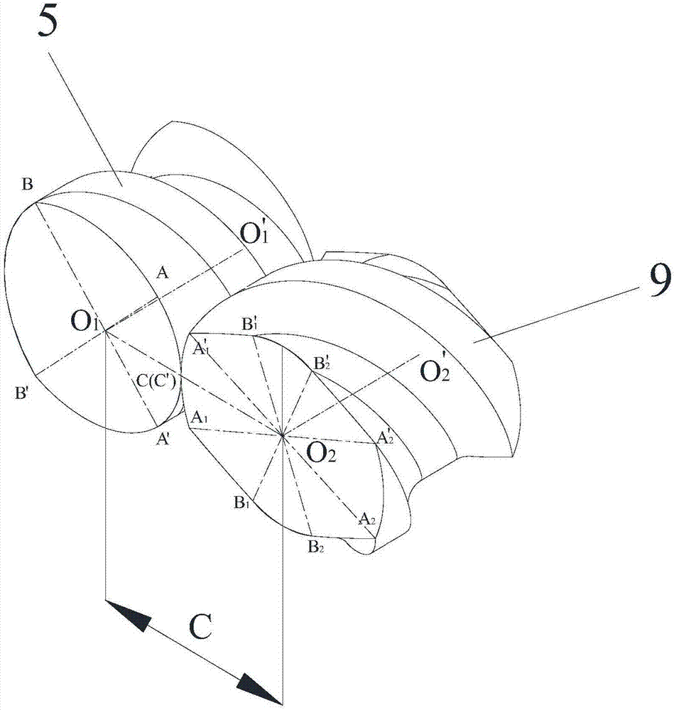
[0049] This embodiment is a kind of co-rotating differential speed twin-screw extruder with gradually changing number of threads, its structure is as follows Figure 1-6 As shown, it includes a barrel 1 and a screw mechanism. The barrel 1 is provided with an inner cavity 2, and the screw mechanism is installed in the inner cavity. The screw mechanism includes a first screw 3 and a second screw 4, and the first screw and the second screw are connected to each other. Engage, and the outermost edges of the first screw and the second screw are tangent to the inner wall of the inner cavity; the first screw, the second screw and the inner cavity of the barrel form a flow channel; when the first screw and the second screw are in the same direction When rotating, the rotation speed of the first screw is twice the rotation speed of the second screw, and the two screws are always in meshing contact with each other to realize the self-cleaning function. Such as Figure 1-6 As shown, the...

Embodiment 2

[0087] This embodiment is a kind of co-rotating differential multi-screw extruder with gradually changing number of threads. Compared with Embodiment 1, the difference is that the screw mechanism also includes a third screw, and the structure of the third screw is the same as that of the first screw. The screws are the same, and the first screw, the second screw and the third screw are connected in sequence to form an in-line three-screw arrangement.

Embodiment 3

[0089] This embodiment is a kind of co-directional differential multi-screw extruder with gradual change in the number of threads. Compared with Embodiment 1, the difference is that the screw mechanism also includes a third screw, and the structure of the third screw is different from that of the second screw. The screws are the same, and the second screw, the first screw and the third screw are connected in sequence to form an in-line three-screw arrangement.


PUM


Abstract

The invention discloses a co-rotating differential multi-screw extruding machine with the gradually changing type thread number and a machining method thereof. A first threaded rod in the extruding machine comprises two single-start thread elements, three single-start-gradually-changed-to-double-start transition thread elements, a double-start thread element and three double-start-gradually-changed-to-single-start transition thread elements; and a second threaded rod comprises two double-start thread elements, three double-start-gradually-changed-to-four-start transition thread elements, a four-start thread element and three four-start-gradually-changed-to-double-start transition thread elements. According to the machining method, a threaded rod mechanism achieves five enhancement mixing mechanisms by adopting the structure of the threaded rod mechanism, and conducts all-sided enhancement mixing on materials.

Description

technical field [0001] The invention relates to the technical field of twin-screw extruders, in particular to a co-rotating differential-speed multi-screw extruder and a processing method thereof. Background technique [0002] The co-rotating twin-screw extruder with self-cleaning function is a widely used mixing processing equipment at present. This type of equipment mainly includes a barrel and two twin-screws installed in parallel in the inner cavity of the barrel. This type of equipment mainly adopts building block structure to adapt to various material systems. The mixing effect is improved by adopting structures such as multi-thread structure and reinforced kneading block. However, the structure of the flow channel is symmetrical, and it is impossible to introduce tensile field strengthening. Dispersion effect. In order to achieve high dispersibility, a large number of kneading blocks with wider disks are used, and high speed is used to increase the shear rate, which...

Claims


Application Information

Patent Timeline
IPC IPC(8): B29C47/40B29C47/62B29C48/405B29C48/57B29C48/65
CPCB29C48/402B29C48/425B29C48/64B29C48/65B29C48/405B29C48/507B29C48/57B29C48/2513B29C48/2517
Inventor 徐百平喻慧文
Owner 徐百平
Learn More