Reinforced thermoplastic pipe end forming device and method

A technology of enhanced thermoplasticity and tube end forming, which is applied to tubular objects, other household appliances, household appliances, etc., can solve problems such as difficult interfaces, RTP service life, etc., and achieve good economic benefits, good molding effects, and simple overall structure.

Active Publication Date: 2017-08-11
王庆昭
View PDF14 Cites 2 Cited by
  • Summary
  • Abstract
  • Description
  • Claims
  • Application Information

AI Technical Summary

Problems solved by technology

[0006] The purpose of the present invention is to overcome the deficiencies in the prior art, seek to design a reinforced thermoplastic composite pipe end forming device and method, and solve the problem that t

Method used


Image

  • Reinforced thermoplastic pipe end forming device and method
  • Reinforced thermoplastic pipe end forming device and method
  • Reinforced thermoplastic pipe end forming device and method

Examples


Embodiment 1

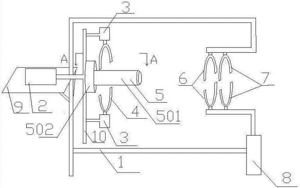
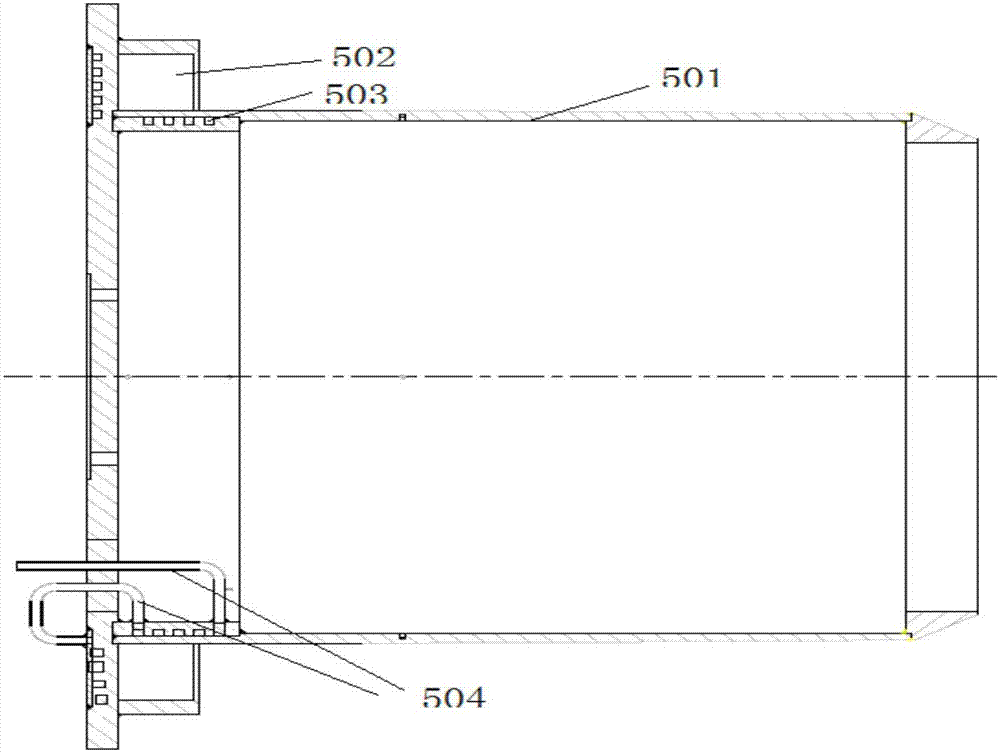
[0032]The main structure of the RTP pipe end forming device involved in this embodiment includes a first bracket 1, an oil cylinder 2, a forming cylinder 3, a movable forming block 4, a forming mold 5, a fixed forming block 6, a fixed clamp 7, a fixed clamping cylinder 8, Support plate 9 and the second support 10, the middle part of the first support 1 of the vertically arranged rectangular frame structure is provided with support plate 9 horizontally, is provided with oil cylinder 2 horizontally on support plate 9, and the end of oil cylinder 2 and the vertically arranged first The two brackets 10 are connected by bolts or riveting. The middle part of the second bracket 10 is horizontally provided with a molding die 5. The molding die 5 includes an inner mold 501, an outer mold 502, an oil passage 503 and an oil pipe 504. The inner mold 501 of the core structure is horizontally fitted with an annular outer mold 502, there is an annular gap between the outer mold 502 and the in...

Embodiment 2

[0040] The difference between this embodiment and embodiment 1 is: the RTP pipe end forming method,

[0041] (1) Start the forming cylinder 3: first start the forming cylinder 3, the forming cylinder 3 drives the movable forming block 4 to move vertically up and down, and the movable forming block 4 is clamped on the forming mold 5;

[0042] (2) Fix the RTP tube: then place the pipe end of the RTP tube to be sealed on the fixed forming block 6 and the fixed fixture 7, start the fixed clamping cylinder 8, and the fixed clamping cylinder 8 drives the lower semicircle of the fixing fixture 7 to be vertical Move upwards so that the RTP tube to be sealed is clamped and fixed;

[0043] (3) Forming: Then start the oil cylinder 2, and the oil cylinder 2 pushes the forming mold 5 forward, so that the end of the RTP pipe is close to the movable forming block 4, and the heat conduction oil is passed, and the temperature of the heat conduction oil is set to 180°C, and the electric heating...

Embodiment 3

[0047] The difference between this example and Example 2 and Example 3 is: the temperature of the heat transfer oil in step (3) is 200°C, and the heating temperature of the electric heating plate is set to 200°C; step (4) is to stop heating after 1.5 hours ; Step (5) is after cooling for 45 minutes, the oil cylinder 2 retreats.


PUM

PropertyMeasurementUnit
Diameteraaaaaaaaaa
Nominal outer diameteraaaaaaaaaa

Abstract

The invention belongs to the technical field of mechanical equipment, and relates to a pipe end forming device and a pipe end forming method, in particular to a reinforced thermoplastic pipe (RTP) end forming device and a reinforced thermoplastic pipe end forming method. The reinforced thermoplastic pipe end forming device and the reinforced thermoplastic pipe end forming method are applied to the pipe machining and manufacturing industry and are used in pipe port manufacturing occasions; the problems that the connection is difficult and the service life of a RTP is shortened since a middle reinforcement layer is exposed to the air are solved, the butting efficiency can be improved effectively and the service life of the RTP can be prolonged; a chamfer is formed at the end part of an internal mould of the reinforced thermoplastic pipe end forming device, so that RTP penetration is facilitated; the diameter of the internal mould is greater than the internal diameter of the RTP, so that during pipe end forming, an expanding effect is exerted on the RTP, and pipe welding is facilitated; hot oil is added to an oil duct, so that an internal layer of the RTP can be heated; the flanging height L is 1.5-2 times of the thickness of the pipe wall of a solid wall at the same pressure rating, so that the pipe end welding safety is guaranteed; and the reinforced thermoplastic pipe end forming device is simple in overall structure, reliable in principle, good in pipe end forming effect, easy and simple to operate, and has good economic benefits and broad market prospects.

Description

[0001] Technical field: [0002] The invention belongs to the technical field of mechanical equipment, and relates to a pipe end forming device and method, in particular to a reinforced thermoplastic composite pipe end forming device and method, which are used in the pipe processing and preparation industry and in pipe end processing occasions. [0003] Background technique: [0004] Reinforced thermoplastic composite pipe (RTP for short) is a structural wall pipe. Compared with ordinary wall pipes, it has unique and significant advantages: it can withstand high working pressure, corrosion resistance, while maintaining flexibility similar to HDPE pipes, It can supply coils with a continuous length of hundreds of meters or even thousands of meters. Therefore, RTP is widely used in industry. RTP usually has a three-layer structure, the inner layer is a thermoplastic such as HDPE, the middle layer is a reinforced layer made of glass fiber, aramid fiber, steel wire or other high-s...

Claims


Application Information

Patent Timeline
IPC IPC(8): B29C57/04B29C57/10B29C35/04B29L23/00
CPCB29C35/041B29C57/04B29C57/10B29C2035/043B29L2023/22
Inventor 王庆昭王大鹏秦升学张战欢孙岩梅连鹏
Owner 王庆昭
Why Eureka
Try Eureka