Fuel pump with outlet valve in piston and fuel path of flushing actuator

A fuel path and fuel pump technology, applied to fuel injection devices with stress-reducing measures, fuel injection devices with piezoelectric elements or magnetostrictive elements, fuel injection pumps, etc., can solve fuel pump efficiency deterioration, delivery It can reduce the flow resistance, uniform cooling, compact structure and other problems.

Active Publication Date: 2020-08-11
ROBERT BOSCH GMBH
View PDF1 Cites 0 Cited by
  • Summary
  • Abstract
  • Description
  • Claims
  • Application Information

AI Technical Summary

Problems solved by technology

This configuration has the disadvantage that the waste heat of the actuator can be transferred directly to the cylinder and thus also to the fuel located in the delivery chamber
This can lead to poor fuel pump efficiency, or even complete failure of the required delivery volume

Method used


Image

  • Fuel pump with outlet valve in piston and fuel path of flushing actuator
  • Fuel pump with outlet valve in piston and fuel path of flushing actuator
  • Fuel pump with outlet valve in piston and fuel path of flushing actuator

Examples


Embodiment Construction

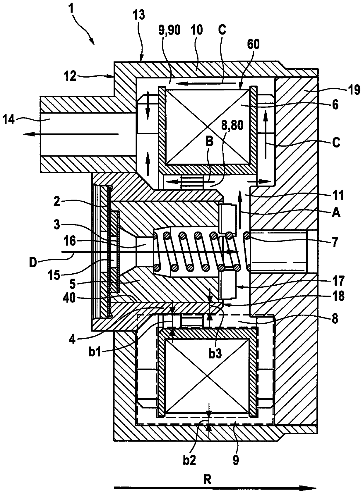
[0029] Refer below figure 1 A fuel pump 1 according to a first preferred embodiment of the present invention will be described in detail. Additionally, with figure 1 A method for operating the fuel pump 1 is described.

[0030] as from figure 1As can be seen in , the fuel pump 1 according to the invention has an inlet valve 2, an outlet valve 3, a cylinder 4, a piston 5 arranged in the cylinder 4, a heat generating actuator 6 for operating the piston 5, and a helical spring In the form of a reset element 7 for returning the piston 5 into the initial position. The fuel pump 1 is mounted, for example, in a fuel tank not shown here.

[0031] An inlet valve 2 is arranged in the end face of the cylinder 4 . The inlet valve 2 is fluidically connected to the fuel tank via a fuel line (not shown here). During the intake phase of the fuel pump 1 , fuel flows from the fuel tank through the inlet valve 2 into the compression chamber 15 formed within the cylinder 4 . The compressio...


PUM


Abstract

The invention discloses a fuel pump having an outlet valve in the piston and a fuel path flowing around the actuator. The fuel pump for delivering fuel, comprises a casing (10), a cylinder (4), a piston (5) which is arranged in the cylinder (4), a heat-producing actuator (6) for actuating the piston (5), and a return element (7) for returning the piston (5) to a starting position, a first gap (8), which is formed at the heat-producing actuator (6), in particular between the cylinder (4) and the heat-producing actuator (6), wherein a first fuel path (80) passes through the first gap (8), an inlet valve (2), an outlet valve (3), wherein the outlet valve (3) is arranged in the piston (5) and the piston (5) has a passage (16), via which a fuel can flow from the outlet valve (3) in the direction of the first gap (8).

Description

technical field [0001] The invention relates to a fuel pump for delivering fuel which can be used, for example, in vehicles, in particular motorcycles or other small motorcycles such as quadricycles or snowmobiles. Another aspect of the invention relates to a method for operating such a fuel pump. Background technique [0002] Such a fuel pump is disclosed, for example, in document GB 2478876B. This is a fuel pump in the form of an electromagnetic piston pump with an inlet valve, an outlet valve, a delivery chamber for delivering fuel, a piston arranged in a cylinder, a heat generating unit in the form of a solenoid coil for actuating the piston. actuator, and a reset element for resetting the piston into the initial position, wherein the heat-generating actuator is arranged directly on the cylinder. This embodiment has the disadvantage that the residual heat of the actuator can be transferred directly to the cylinder and thus also to the fuel located in the delivery chamb...

Claims


Application Information

Patent Timeline
Patent Type & Authority Patents(China)
IPC IPC(8): F02M37/08F02M59/46F02M37/20F02M37/04F02M59/10F02M59/02F02M59/44
CPCF02M37/043F02M37/08F02M37/20F02M59/02F02M59/10F02M59/44F02M59/462F02M37/04F02M59/025F02M69/02F02M2200/03F02M2200/21F04B17/046F04B39/00F04B53/127F02M59/46
Inventor J·里克尔特A·普利施S·芙洛
Owner ROBERT BOSCH GMBH
Why Eureka
Try Eureka