Method of correcting various array errors in wave-reaching direction estimation

A technology of direction of arrival estimation and array error, which is applied to the radio wave direction/bias determination system, the direction/bias determination system, the direction/bias determination electromagnetic system and other directions, which can solve the problems of low processing speed and high complexity, To achieve the effect of reducing errors

Inactive Publication Date: 2017-08-11
HARBIN INST OF TECH
View PDF4 Cites 25 Cited by
  • Summary
  • Abstract
  • Description
  • Claims
  • Application Information

AI Technical Summary

Problems solved by technology

[0003] The purpose of the present invention is to solve the disadvantages that the existing array error processing method often corrects one type of error,

Method used


Image

  • Method of correcting various array errors in wave-reaching direction estimation
  • Method of correcting various array errors in wave-reaching direction estimation
  • Method of correcting various array errors in wave-reaching direction estimation

Examples


specific Embodiment approach 1

[0020] Specific Embodiment 1: The method for correcting multiple array errors in direction of arrival estimation in this embodiment, the uniform linear array used in the method is composed of M array elements, and N far-field signal sources are spatially distributed, , azimuth Angle θ i is the quantity to be estimated, i=1,2,...,N, the number of array elements and the number of signal sources satisfy Wherein L is the number of mutual coupling matrix parameters, and r represents the azimuth dimension of the array system; it is characterized in that, the method includes:

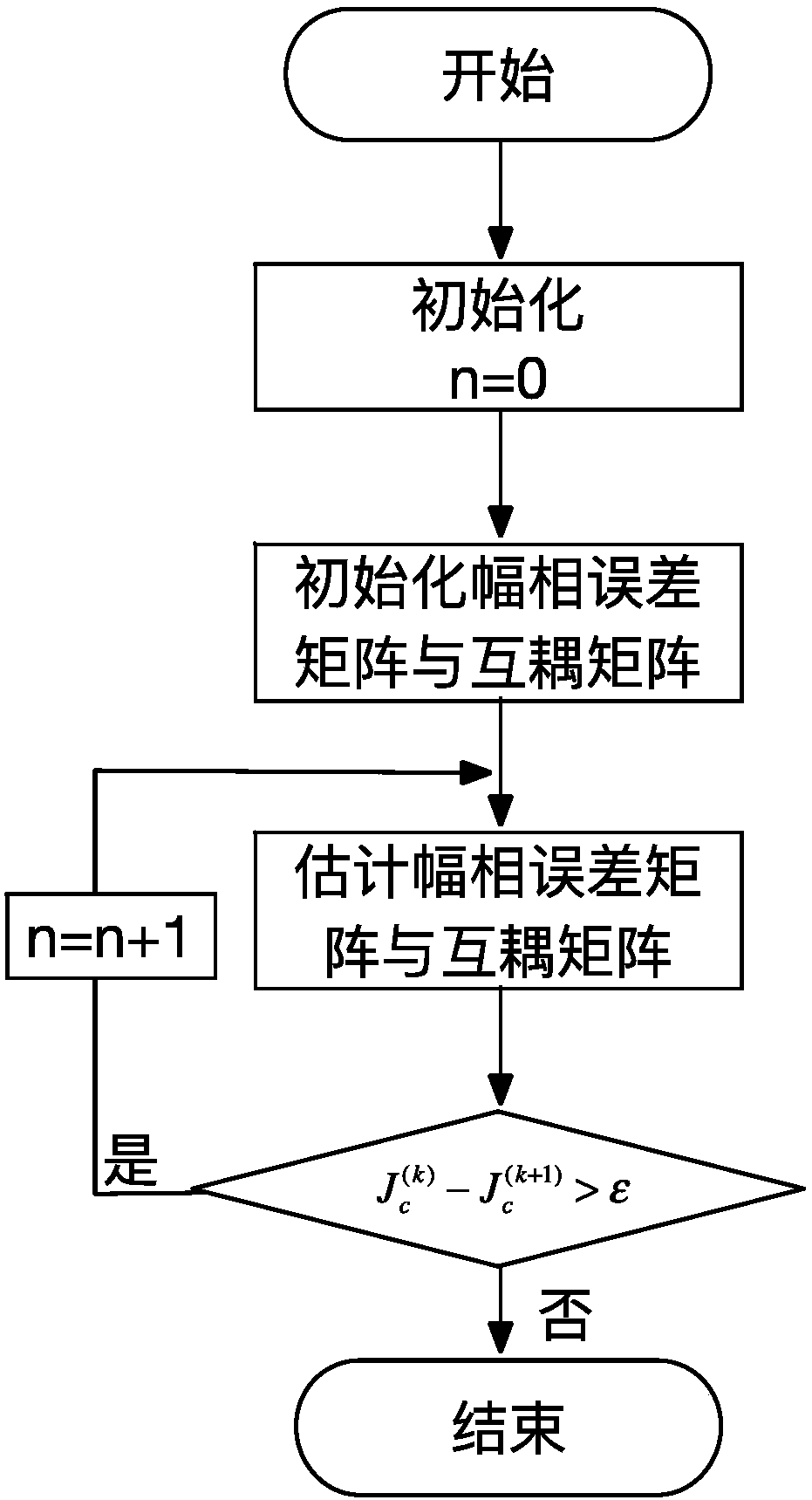
[0021] Step 1. Initialize the iteration count value n, obtain the amplitude-phase inconsistency error matrix Γ and the mutual coupling matrix C; obtain the eigendecomposition covariance matrix according to the MUSIC algorithm Noise subspace matrix U and noise subspace estimation matrix

[0022] Step 2. Define the spatial spectrum Where a(θ) is the steering vector; is the estimated value of the amplit...

specific Embodiment approach 2

[0031] Specific implementation mode two: the difference between this implementation mode and specific implementation mode one is that step four is specifically:

[0032] Keep DOA estimated angle and mutual coupling matrix unchanged, the calculation formula

[0033]

[0034] k is the current iteration count value; the vector formed by the diagonal elements of the amplitude-phase inconsistency error matrix Γ is δ=[Γ 11 ,Γ 22 ,…,Γ MM ], Q 1 (n)=diag{a(θ n )}.

[0035] use expressions Enter the formula as δ to obtain the estimated value of the amplitude-phase inconsistency matrix of the kth iteration in get The process is to select the first array element as the reference point, under the constraint condition δ H w=1, w=[1,0,…,0] to minimize J c .

[0036] Other steps and parameters are the same as those in Embodiment 1.

specific Embodiment approach 3

[0037] Specific implementation mode three: the difference between this implementation mode and specific implementation mode one or two is that step five is specifically:

[0038] Keep DOA Estimates Estimated value of magnitude and phase inconsistency error unchanged, the calculation formula

[0039]

[0040] k is the current iteration count value; use expressions Enter the formula as the initial value of c to get The estimation result of , the constraint condition is C 11 = 1, written as an equation Usually let W 1 =[1,0,…,0] T , u=1. Then by the expression c i =C 1i (i=1,2,…,L) to get the mutual coupling matrix estimated value. in

[0041]

[0042] The meaning of iteration in this embodiment is that the Bring into J initially as c c The first iteration is performed in the expression, the value of c is constantly changing during this process, and the result of the iteration is as the estimated results. Then use the estimated result as the in...


PUM

PropertyMeasurementUnit
Snraaaaaaaaaa

Abstract

The invention relates to an error estimation method in wave-reaching direction estimation and in particular to a method of correcting various array errors in wave-reaching direction estimation. In order to overcome the defects that the processing speed is relatively low and the complexity is relatively high as an existing array error processing method always corrects one error, the invention provides the method of correcting various array errors in wave-reaching direction estimation. The method comprises the following steps of: acquiring an amplitude and phase error matrix and a cross coupling array; obtaining a characteristic decomposition covariance matrix, a noise sub-spatial matrix and an estimation matrix according to a MUSIC algorithm; defining a spatial spectrum; searching for DOA estimation of N peak values in the spatial spectrum; solving an estimated value of an amplitude and phase inconsistency error matrix; solving an estimated value of the cross coupling matrix; calculating a cost function; giving a threshold, and if the difference between the adjacent iterated cost functions twice is greater than the threshold, performing continuous iteration; and if not, escaping circulation to obtain a to-be-estimated parameter. The method provided by the invention is suitable for estimating the wave-reaching direction in the presence of the array error.

Description

technical field [0001] The invention relates to an error estimation method in the direction of arrival estimation, in particular to a method for correcting various array errors in the direction of arrival estimation. Background technique [0002] Direction of arrival estimation is an important research direction in array signal processing, and has a very broad application prospect in many fields such as radar, communication, and sonar. In spatial spectrum estimation, array error is an unavoidable form of error, which can lead to the discrepancy between the array flow pattern and the assumed model, so that the performance of the DOA algorithm based on the ideal model is significantly reduced, which will affect the practical application of the DOA algorithm , so it is of practical significance to carry out research on making direction of arrival estimation more stable in practical applications. Traditional array error processing methods often correct for a certain type of err...

Claims


Application Information

Patent Timeline
IPC IPC(8): G01S3/14G01S3/782G01S3/802
CPCG01S3/14G01S3/782G01S3/802
Inventor 郭庆苏南池王秀红邵欣业高天娇张宇萌
Owner HARBIN INST OF TECH
Why Eureka
Try Eureka