
Mounting structure and method of electrical cubicle

A technology of installation structure and installation method, applied in electrical components, substation/distribution device casing, substation/switch layout details, etc., can solve the problems of high construction intensity, large working space, hidden safety hazards, etc., and reduce the installation and operation space. , Easy to adjust the position, to ensure the effect of environmental protection requirements

Pending Publication Date: 2017-08-11
四川电力设计咨询有限责任公司
View PDF14 Cites 2 Cited by
  • Summary
  • Abstract
  • Description
  • Claims
  • Application Information

AI Technical Summary

Problems solved by technology

There are problems with this fixing method: 1) arc spot welding produces open flames, and the fire hazard classification is higher or the operation in certain specific environments is restricted; 2) arc spot welding has irritating smoke and dust, which causes environmental pollution and increases worker protection Measures and burdens; 3) The position of the electrical screen cabinet cannot be adjusted after it is fixed, and the accumulation of construction errors often results in the insufficient size of the reserved screen space to be discarded; 4) A row of electrical screen cabinets must be installed from the middle screen position to both sides, so that two The side screen position is reserved, which greatly reduces the flexibility of the layout of the electrical screen cabinet and limits the plan layout of the secondary equipment room; The internal equipment is damaged, and at the same time, it is easy to cause the cable connection of the electrical screen cabinet in normal operation to be loose, which brings potential safety hazards; 6) The installation of the electrical screen cabinet requires a large working space in front of and behind the screen, and it cannot be carried out when the space is limited.

Method used


Image

  • Mounting structure and method of electrical cubicle

Examples


Embodiment Construction

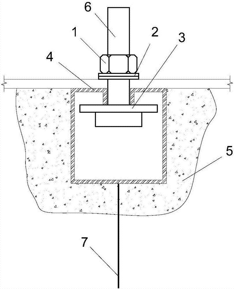
[0015] Such as figure 1 The installation structure of the electric screen cabinet of the present invention shown has a strip-shaped metal fixing part 4 for being arranged in the concrete 5. The strip-shaped metal fixing part 4 adopts C-shaped steel prefabricated in the factory, and is connected to the grounding structure through the anchor bar 7 grounding. The strip-shaped metal fixing part 4 is a hollow structure, and an opening is arranged on the upper end thereof along the axial direction. A threaded fastener 6 of a bolt structure protruding from the opening is provided in the hollow structure, and the length of the main body of the threaded fastener 6 is greater than the radial length of the strip metal fastener 4 . The protruding part of the threaded fastener 6 is provided with a nut 1 matched with it through a washer 2 . The bottom of the threaded fastener 6 is stuck on the lower edge of the opening of the strip metal fixing part 4 through the backing plate 3 .

[001...


PUM


Abstract

The invention relates to a mounting structure and method of an electrical cubicle. The mounting structure is provided with a stripy metal fixing part which is arranged in concrete, wherein the stripy metal fixing part is of a hollow structure, and an opening is axially formed in the upper end of the stripy metal fixing part; a thread fastening part which extends out from the opening is arranged in the hollow structure; a nut is arranged at the extended part of the thread fastening part and fits the thread fastening part; the bottom part of the thread fastening part is clamped to the lower edge of the opening of the stripy metal fixing part. With the adoption of the mounting structure, the electrical cubicle can be simply and quickly mounted, so that the mounting efficiency of the electrical cubicle can be greatly improved; in addition, the position is easily adjusted, thus the mounting operation space is greatly reduced; and the environmental protection requirement is met in the mounting process.

Description

technical field [0001] The invention relates to an installation structure and an installation method of an electric screen cabinet in a power system. Background technique [0002] In the power system, the electrical screen cabinets are mostly installed on the pre-embedded channel steel because they need to be safely grounded. At present, the common fixing method is to fix the cabinet body to the channel steel by spot welding. There are problems with this fixing method: 1) arc spot welding produces open flames, and the fire hazard classification is higher or the operation in certain specific environments is restricted; 2) arc spot welding has irritating smoke and dust, which causes environmental pollution and increases worker protection Measures and burdens; 3) The position of the electrical screen cabinet cannot be adjusted after it is fixed, and the accumulation of construction errors often results in the insufficient size of the reserved screen space to be discarded; 4) A ...

Claims


Application Information

Patent Timeline
Patent Type & Authority Applications(China)
IPC IPC(8): H02B1/30
CPCH02B1/303
Inventor 胡德峰潘峰程科陈浩胡稼彭磊雷云川陈洛风罗显通王川梅毅赵守贵张利丹廖梓屹杜洪波肖德秋刘斌王云柳肖健一代明明董泽兴
Owner 四川电力设计咨询有限责任公司
Learn More