Part polishing equipment for hardware tool machining

A technology for parts and hardware, applied in the field of parts polishing equipment for hardware processing, can solve the problems of low polishing efficiency, cumbersome operation, uneven polishing, etc.

Inactive Publication Date: 2017-08-15
河北东海特钢集团有限公司
View PDF9 Cites 11 Cited by
  • Summary
  • Abstract
  • Description
  • Claims
  • Application Information

AI Technical Summary

Problems solved by technology

[0006] In order to overcome the disadvantages of cumbersome operation, low polishing efficiency and uneven polishing in the current parts polishing device for hardware tool processing, the technical problem to be solved by the present invention is to provide a hardware tool with convenient operation, high polishing efficiency and smooth polishing Polishing equipment for machining parts

Method used


Image

  • Part polishing equipment for hardware tool machining
  • Part polishing equipment for hardware tool machining
  • Part polishing equipment for hardware tool machining

Examples


Embodiment 1

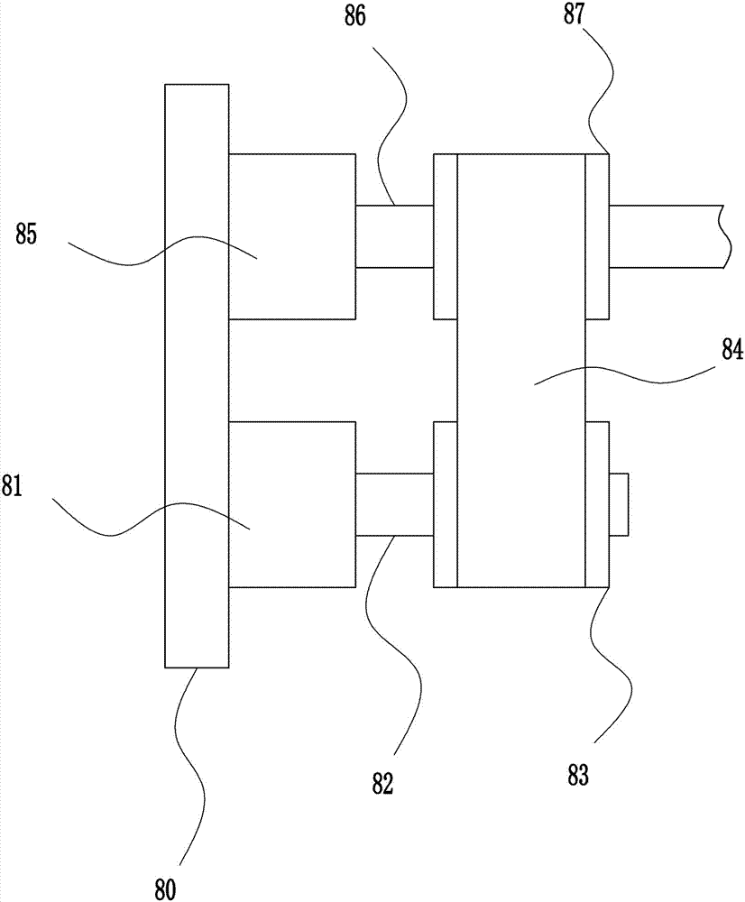
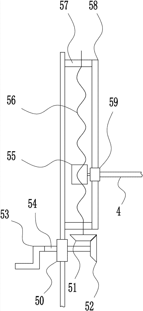
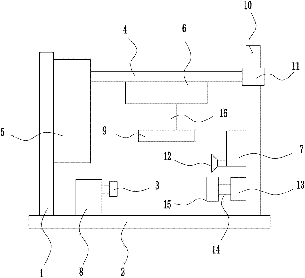
[0034] A kind of parts polishing equipment for metal processing, such as Figure 1-5 As shown, it includes a left frame 1, a base plate 2, a first fixed sleeve 3, a fixed plate 4, a lifting device 5, a first rotating device 6, an air spray device 7, a second rotating device 8, a polishing wheel 9, and a first guide post 10. The first guide sleeve 11, the nozzle 12, the first bearing seat 13, the first rotating shaft 14, the second fixed sleeve 15 and the second rotating shaft 16, the left frame 1 is welded on the left side of the top of the bottom plate 2, and the left frame 1 is set on the right side There is a lifting device 5, the right side of the lifting device 5 is welded with a fixed plate 4, the right side of the top of the base plate 2 is welded with a first guide post 10, the first guide post 10 is covered with a first guide sleeve 11, the right side of the fixed plate 4 is connected to the second A guide sleeve 11 is connected on the left side, a second rotating dev...

Embodiment 2

[0036] A kind of parts polishing equipment for metal processing, such as Figure 1-5 As shown, it includes a left frame 1, a base plate 2, a first fixed sleeve 3, a fixed plate 4, a lifting device 5, a first rotating device 6, an air spray device 7, a second rotating device 8, a polishing wheel 9, and a first guide post 10. The first guide sleeve 11, the nozzle 12, the first bearing seat 13, the first rotating shaft 14, the second fixed sleeve 15 and the second rotating shaft 16, the left frame 1 is welded on the left side of the top of the bottom plate 2, and the left frame 1 is set on the right side There is a lifting device 5, the right side of the lifting device 5 is welded with a fixed plate 4, the right side of the top of the base plate 2 is welded with a first guide post 10, the first guide post 10 is covered with a first guide sleeve 11, the right side of the fixed plate 4 is connected to the second A guide sleeve 11 is connected on the left side, a second rotating dev...

Embodiment 3

[0039] A kind of parts polishing equipment for metal processing, such as Figure 1-5 As shown, it includes a left frame 1, a base plate 2, a first fixed sleeve 3, a fixed plate 4, a lifting device 5, a first rotating device 6, an air spray device 7, a second rotating device 8, a polishing wheel 9, and a first guide post 10. The first guide sleeve 11, the nozzle 12, the first bearing seat 13, the first rotating shaft 14, the second fixed sleeve 15 and the second rotating shaft 16, the left frame 1 is welded on the left side of the top of the bottom plate 2, and the left frame 1 is set on the right side There is a lifting device 5, the right side of the lifting device 5 is welded with a fixed plate 4, the right side of the top of the base plate 2 is welded with a first guide post 10, the first guide post 10 is covered with a first guide sleeve 11, the right side of the fixed plate 4 is connected to the second A guide sleeve 11 is connected on the left side, a second rotating dev...


PUM


Abstract

The invention relates to polishing equipment, in particular to part polishing equipment for hardware tool machining. The part polishing equipment for hardware tool machining aims at achieving the technical effects that operation is convenient, the polishing efficiency is high, and polishing is smooth. In order to achieve the technical effects, the part polishing equipment for hardware tool machining is provided and comprises a left frame, a bottom plate, a first fixing sleeve, a fixing plate, a lifting device, a first rotating device, an air spraying device, a second rotating device, a polishing wheel, a first guide column and the like. The left frame is welded to the left side of the top of the bottom plate. The lifting device is arranged on the right side of the left frame. The fixing plate is welded to the right side of the lifting device. The first guide column is welded to the right side of the top of the bottom plate. A rocking handle is rotated to drive a third rotating shaft to rotate, the third rotating shaft drives a second bevel gear to rotate, the second bevel gear drives a lead screw to rotate through a first bevel gear, and the lead screw and a nut are mutually matched.

Description

technical field [0001] The invention relates to a polishing device, in particular to a component polishing device for metal processing. Background technique [0002] Hardware: traditional hardware products, also known as "hardware". Refers to the five metals of gold, silver, copper, iron, and tin. After manual processing, it can be made into works of art or metal devices such as knives and swords. Hardware in modern society is more extensive, such as hardware tools, hardware parts, daily hardware, construction hardware and security supplies. Most hardware products are not final consumer goods. [0003] Polishing refers to the use of mechanical, chemical or electrochemical action to reduce the surface roughness of the workpiece to obtain a bright and smooth surface. It is a modification process on the surface of the workpiece by using polishing tools and abrasive particles or other polishing media. Polishing does not improve the dimensional accuracy or geometric shape ac...

Claims


Application Information

Patent Timeline
Patent Type & Authority Applications(China)
IPC IPC(8): B24B29/02B24B41/06B24B47/12B24B41/00B24B41/02
CPCB24B29/02B24B41/00B24B41/005B24B41/02B24B41/062B24B47/12
Inventor 不公告发明人
Owner 河北东海特钢集团有限公司
Why Eureka
Try Eureka