Tilt-rotor unmanned aerial vehicle

A tilt-rotor and unmanned aerial vehicle technology is applied in the field of unmanned aerial vehicles to achieve the effects of good stability, long battery life and high control efficiency

Pending Publication Date: 2017-08-15
北京天宇新超航空科技有限公司
View PDF6 Cites 42 Cited by
  • Summary
  • Abstract
  • Description
  • Claims
  • Application Information

AI Technical Summary

Problems solved by technology

[0003] The purpose of the present invention is to overcome the technical defects of the existing electric tilt-rotor U

Method used


Image

  • Tilt-rotor unmanned aerial vehicle
  • Tilt-rotor unmanned aerial vehicle
  • Tilt-rotor unmanned aerial vehicle

Examples


Embodiment Construction

[0034] The technical solutions of the present invention will be further described below through examples in conjunction with the accompanying drawings, but the scope of protection is not limited thereto.

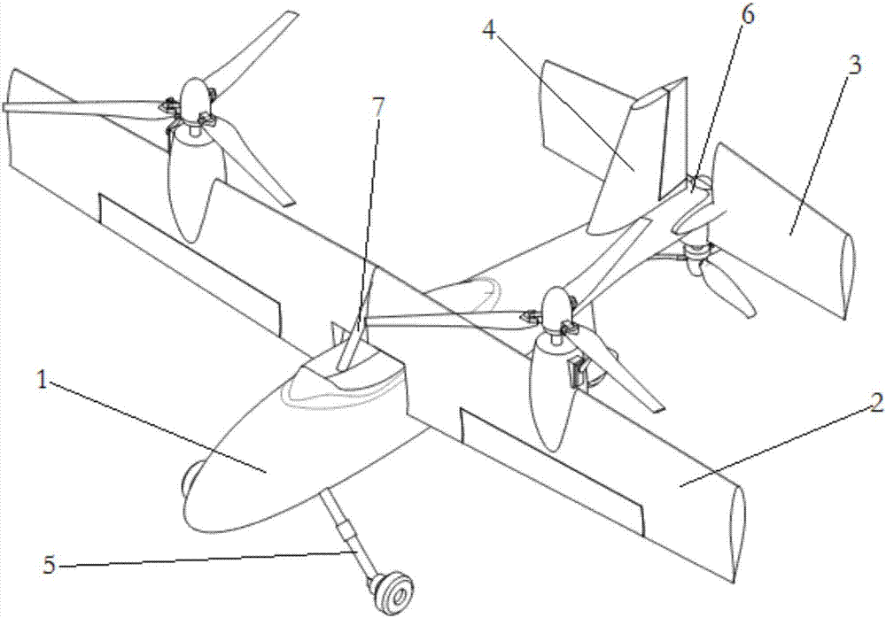
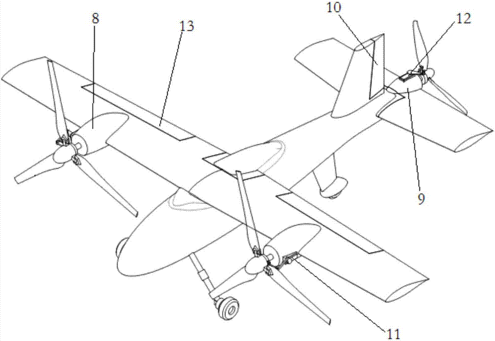
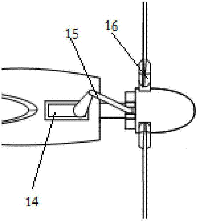
[0035] An embodiment of the present invention provides an oil-powered variable-pitch tilt-rotor UAV, which is mainly composed of a body structure, a power system, a control system and a tilting mechanism. Its main features are: powered by fuel, the wings and horizontal tail can be tilted at a large angle through the tilting mechanism inside the fuselage to realize the switching between multi-rotor mode and fixed-wing mode, and each power unit is also equipped with a variable The distance device can effectively improve the flight efficiency.

[0036] The airframe structure above is composed of fuselage 1, tiltable wing 2, tiltable horizontal tail 3, vertical tail 4, and landing gear 5. The airframe structure adopts a streamlined design, has a good aerodynamic shape, and great...


PUM


Abstract

A tilt-rotor unmanned aerial vehicle comprises a fuselage, tilted wings, tilted tail planes, a vertical empennage, a power system and a landing gear. The tilt-rotor unmanned aerial vehicle is characterized in that the power system comprises wing power devices arranged on the wings, tail plane power devices arranged on the tail planes, oil tanks and oil transferring pipelines, and the power devices and the oil tanks are distributed symmetrically on the two sides of the vertical symmetrical face of the fuselage. The wing power devices and/or the empennage power devices comprise pinch control mechanisms, and the pinch control mechanisms can adjust angles between paddles of a propeller and the axis of the paddles through mechanical transmission. The wings and the tail planes can tilt at large angles through tilting mechanisms, and free conversion between a multi-rotor mode and a fixed wing mode can be achieved under control of a control system.

Description

technical field [0001] The invention relates to the field of unmanned aerial vehicles, in particular to an oil-powered variable-pitch tilt-rotor unmanned aerial vehicle. Background technique [0002] With the development of UAV technology, many UAVs with new layouts have begun to appear in people's field of vision, including tilt-rotor UAVs. Tilt-rotor UAV is a new type of UAV that combines the advantages of fixed-wing UAV and multi-rotor UAV. A more efficient aircraft. At this stage, most of the tilt-rotor UAVs on the market use lithium batteries as power. Although lithium batteries have the advantages of large specific energy, large specific volume, and no pollution, it is still difficult to meet the long-term voyage of today's industrial-grade UAVs. time and heavy load requirements. Contents of the invention [0003] The purpose of the present invention is to overcome the technical defects of the existing electric tilt-rotor UAV, and provide an oil-powered variable-p...

Claims


Application Information

Patent Timeline
IPC IPC(8): B64C27/26B64C27/28B64C27/59B64C29/00B64C11/32
CPCB64C11/32B64C27/26B64C27/28B64C27/59B64C29/0033B64U10/25B64U10/10B64U50/14
Inventor 胡龙王一博
Owner 北京天宇新超航空科技有限公司
Why Eureka
Try Eureka