Double-channel ERG (electroretinogram) portable detection system with pre-amplifier

A preamplifier, electroretinogram technology, applied in the direction of sensors, diagnostic recording/measurement, eye testing equipment, etc., can solve the problems of inaccurate judgment of eye diseases, long detection time, inaccurate detection and other problems of patients, and achieve reduction Effect of External Signal Interference

Pending Publication Date: 2017-08-18
SHENZHEN MEGMEET ELECTRICAL CO LTD
View PDF5 Cites 3 Cited by
  • Summary
  • Abstract
  • Description
  • Claims
  • Application Information

AI Technical Summary

Problems solved by technology

[0018] The traditional signal amplifier amplifying circuit and signal processing circuit perform digital signal processing on the retinal electrical signal. Due to technical reasons, it is far away from the contact lens electrode (ERG-J) and the ground electrode, but the problems brought about cannot be ignored. There is an electrical signal output. Weak, too many crosstalk signals, and inaccurate detection. Although the signal amplifier can still process the electrical signal to a certain extent, the ERG waveform formed cannot be well recognized and analyzed in digital processing. Disease diagnosis is not accurate enough
[0019] At present, medical flash stimulators and electrographic recorders are special equipment with large volume, which are heavy and inconvenient to move, and the cost of equipment is very high.
At the same time, the existing single-channel ERG detection has certain accidental deviation and interference, and it is prone to deviation in analysis. It often requires multiple ERG detections on patients to make an accurate judgment, and the detection time takes a long time, which brings inconvenience to patients.

Method used


Image

  • Double-channel ERG (electroretinogram) portable detection system with pre-amplifier
  • Double-channel ERG (electroretinogram) portable detection system with pre-amplifier
  • Double-channel ERG (electroretinogram) portable detection system with pre-amplifier

Examples


Embodiment Construction

[0044] In order to make the technical means realized by the present invention clear, the present invention will be further described below in conjunction with the accompanying drawings.

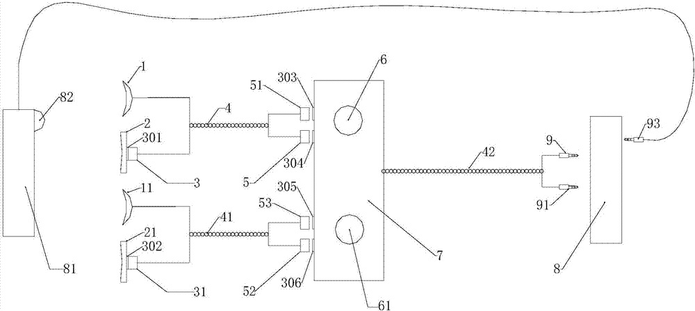
[0045] Such as figure 1 As shown, the present invention is a dual-channel electroretinogram (ERG) portable detection system with a preamplifier, including a miniature preamplifier 7, a flash stimulator 81, a first group of detection electrodes and a second group of detection electrodes, The receiving end of the miniature pre-signal amplifier 7 is provided with a first magnetic joint 303, a second magnetic joint 304, a third magnetic joint 305 and a fourth magnetic joint 306, and the first group of detection electrodes includes a corneal contact electrode 1 and a ground Electrode 2, the second group of detection electrodes includes a cornea contact electrode 11 and a ground electrode 21, the signal line of the cornea contact electrode 1 and the connection line of the ground electrode 2 form a...


PUM


Abstract

The invention provides a double-channel ERG (electroretinogram) portable detection system with a pre-amplifier. The system comprises a miniature signal preamplifier, a flash stimulator, a first group of detection electrodes and a second group of detection electrodes, the miniature signal preamplifier is provided with four magnetic joints, each group of detection electrodes include a cornea contact electrode and a ground electrode, a signal line of each cornea contact electrode and a connecting line of each ground electrode form a twisted pair, one end of each twisted pair is connected with the corresponding magnetic joint on the preamplifier through a permanent magnet, two adjustable gain knobs are arranged on the miniature signal preamplifier and used for amplifying signals, and detection signals are amplified and then displayed on a display device of a mobile terminal. The cornea contact electrodes and the ground electrodes are close to the preamplifier, the connecting lines are short, external signal interference is decreased, the twisted pairs offset mutual interference of two channels in detection, the system is small in total size and convenient to use, and an APP (application) of the handheld mobile terminal can conveniently select flash stimulation modes.

Description

[0001] [technical field] [0002] The invention relates to the field of ophthalmic medical technology, in particular to a dual-channel electroretinogram (ERG) portable detection system with a preamplifier. [0003] [Background technique] [0004] Electroretinogram (ERG) has been used clinically for 40 years since Karpe (1945). It is a guide electrode that is in contact with the cornea, and another larger reference electrode, also known as the ground electrode, is placed on the forehead When the retina is stimulated with light, the total electrical response of the retina recorded by the retinal electrodes from the cornea or corresponding parts can be recorded on the oscilloscope of the detection equipment to record a series of visual electrical changes, namely electroretinogram (ERG). According to different stimulation conditions, there are flash ERG, local ERG and multifocal ERG. Electroretinogram is often used to effectively detect retinal ganglion cell diseases such as fundu...

Claims


Application Information

Patent Timeline
Patent Type & Authority Applications(China)
IPC IPC(8): A61B5/0496A61B3/10
CPCA61B3/10A61B5/7225A61B5/398
Inventor 刘勇
Owner SHENZHEN MEGMEET ELECTRICAL CO LTD
Why Eureka
Try Eureka