Autocatalytic denitrification system for sintering flue gas partitioned circulation coupling flue dust

A technology of sintering flue gas and autocatalysis, applied in the field of flue gas denitration system in the field of environmental protection, can solve the problems of increasing SCR denitration operation cost, high consumption and high operation cost, saving investment and denitration operation cost, and reducing flue gas temperature. , The effect of reducing post dust

Active Publication Date: 2020-06-12
武汉钢铁有限公司 +2
View PDF15 Cites 0 Cited by
  • Summary
  • Abstract
  • Description
  • Claims
  • Application Information

AI Technical Summary

Problems solved by technology

There are application cases in the sintering machine flue gas purification projects of Japan's Nippon Steel & Sumitomo Metal, JFE, South Korea's Posco, and China's Taiyuan Iron and Steel Co., Ltd., but its shortcomings are also obvious, such as large investment, high operating costs, and low denitrification efficiency , there is no proper disposal plan for waste activated carbon
[0011] Selective catalytic reduction (SCR) has high denitrification efficiency, but its one-time investment cost is high (the catalyst cost accounts for 30-40% of the total investment cost), and the existing SCR flue gas denitrification technology is generally 350- It is carried out at 450°C, which consumes a lot of heat energy to heat the flue gas after desulfurization, which additionally increases the operating cost of SCR denitrification

Method used


Image

  • Autocatalytic denitrification system for sintering flue gas partitioned circulation coupling flue dust
  • Autocatalytic denitrification system for sintering flue gas partitioned circulation coupling flue dust
  • Autocatalytic denitrification system for sintering flue gas partitioned circulation coupling flue dust

Examples


Embodiment Construction

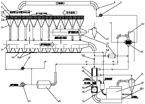
[0041] see image 3 , the system of the present invention includes a sintering machine 2, a bellows 4 is provided under the trolley 2.1 of the sintering machine 2, and the outlet at the bottom of the bellows 4 is connected to a flue gas pipeline, and the sintering machine is successively divided into an ignition section and a machine head along the traveling direction of the trolley 2.1. section, the flue gas rapid heating section and the tail section. The flue gas pipeline is composed of the main flue 5 and the circulating flue gas main flue 12. The main flue 5 is connected with the wind box 4 below the ignition section area, and the main flue 5 is sequentially connected to the tube side or shell side of the denitration flue gas heat exchanger 13, the flue gas heater 16 and the fluidized bed denitrification reactor 10, The flue gas outlet of the fluidized bed denitrification reactor 10 is connected through the shell or tube side of the flue gas dust collector 9, the denitrifi...


PUM


Abstract

The invention relates to a sintering flue gas zoned-circulating coupled soot autocatalysis and denitration system. According to the technical scheme, the sintering flue gas zoned-circulating coupled soot autocatalysis and denitration system comprises a sintering machine, wherein an air box is arranged below a trolley of the sintering machine, an outlet of the bottom of the air box is communicated with a flue gas pipeline, the sintering machine is sequentially divided into an ignition section, a machine head section, a rapid flue gas heating section and a machine tail section in the advancing direction of the trolley, the flue gas pipeline consists of a main flue and a main circulating flue gas flue, the machine tail section, the rapid flue gas heating section and the air box below the ignition section area of the sintering machine are communicated with the main flue, and the air box below the machine head section area is connected with a circulating flue gas cover above the sintering machine through the main circulating flue gas flue and a circulating flue gas dust remover. The sintering flue gas zoned-circulating coupled soot autocatalysis and denitration system is simple, good in denitration effect, high in residual heat recovery rate, small in occupied area, friendly to environment and low in device investment and operating cost and does not need denitration catalysts.

Description

technical field [0001] The invention relates to a flue gas denitrification system in the field of environmental protection, in particular to an autocatalytic denitrification system for sintering flue gas divisional circulation coupled with dust. Background technique [0002] Iron and steel products are typical, the most common and cheap metal materials used in modern society, and they are also the easiest resources to recycle and regenerate. While the steel industry provides high-quality steel, realizes energy conversion, and eliminates social waste, it also attracts attention due to high consumption, high emissions, and high pollution. Taking the sintering process with large emissions of air pollutants as an example, its energy consumption accounts for 10-20% of the total energy consumption of steel production, and the flue gas volume is 1500-2500m 3 / t-s, ring cooling exhaust gas volume is about 2200m 3 / t-s, and the flue gas contains dust, SO 2 , NOx, dioxins, VOCs, he...

Claims


Application Information

Patent Timeline
Patent Type & Authority Patents(China)
IPC IPC(8): B01D53/90B01D53/56
CPCB01D53/8631B01D53/90
Inventor 吴高明吴晓晖姚茜陈旺生卫书杰
Owner 武汉钢铁有限公司
Why Eureka
Try Eureka