Supercharge Your Innovation With Domain-Expert AI Agents!

Disassembly method of hydraulic cylinder piston head

A piston head and hydraulic cylinder technology, applied in the field of hydraulic cylinder production, can solve problems such as personnel injury, hidden dangers of parts and maintenance personnel, deformation of positioning pin holes, etc.

Active Publication Date: 2018-10-30
重庆博创知识产权运营有限公司
View PDF5 Cites 0 Cited by
  • Summary
  • Abstract
  • Description
  • Claims
  • Application Information

AI Technical Summary

Problems solved by technology

When the threaded self-tightening piston head is disassembled, it can only be disassembled by the force of the two fixed pin holes on the upper end of the piston head. At present, there is no disassembly tool for the hydraulic cylinder self-tightening piston head that can quickly and conveniently disassemble the hydraulic cylinder piston head. The use of general tools is low in efficiency and time-consuming, and it is easy to break the positioning pin, deform the positioning pin hole, and slip off the disassembly tool during disassembly, which poses a greater safety hazard to parts and maintenance personnel.
Only two positioning holes can be used on the piston head. Due to the large tightening torque between the piston head and the piston rod, a large torque is required for disassembly, and the depth and diameter of the holes on the piston head are limited. , the disassembly tool cannot be fixed. When a large torque is used and the force is uneven, the disassembly tool will slip off immediately, causing the positioning pin hole to be deformed or personnel injured, which poses a safety hazard and is prone to safety accidents

Method used


Image

  • Disassembly method of hydraulic cylinder piston head
  • Disassembly method of hydraulic cylinder piston head
  • Disassembly method of hydraulic cylinder piston head

Examples


Embodiment 1

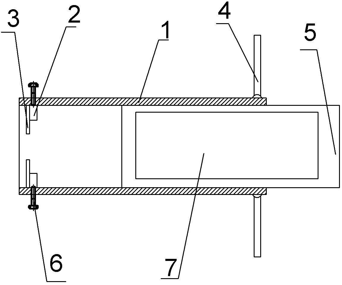
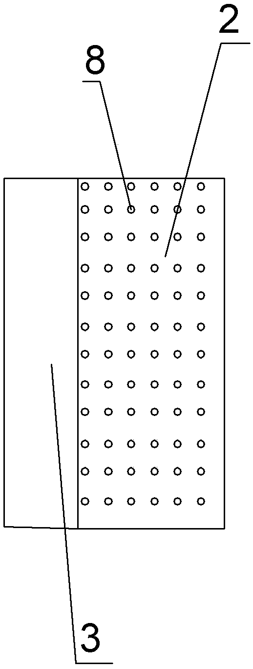
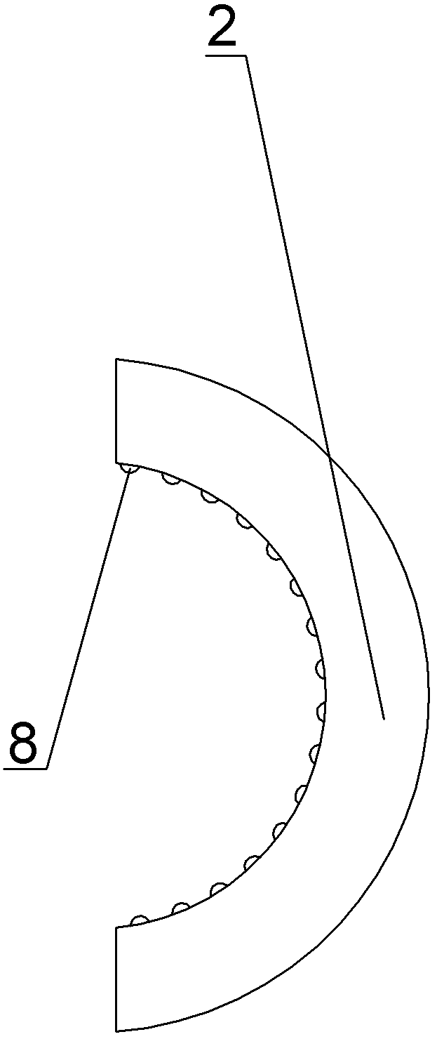
[0016] Embodiment 1: This embodiment is basically as appended Figure 1-3 Shown: a method for disassembling the piston head of a hydraulic cylinder, including a main shaft 5 and a clamping structure, the main shaft 5 is provided with threads, and the clamping structure includes a fixing part 1 and two claws 2, and the two claws 2 and the fixing part One end of 1 is fixedly connected, the fixing part 1 is threadedly connected with the main shaft 5, and the cross section of the claw 2 is semi-circular; the claw 2 is connected with the fixing part 1 through a bolt 6, and a plurality of first fixing blocks 3 are arranged on one side of the claw 2 , The inner surface of the jaw 2 is provided with a plurality of protrusions 8, the main shaft 5 is provided with a magnetic part 7, and the fixing part 1 is made of a metal material, which is iron in this embodiment. The other end of the fixing part 1 is provided with a handle 4, and the fixing part 1 is rotated by the handle 4, which is...

Embodiment 2

[0019] Embodiment 2: The difference between this embodiment and Embodiment 1 is that there is a groove in the claw 2, and the second fixing block 11, the fixing column 10 and the spring 9 are arranged in the groove, and the second fixing block 11 is located in the groove It is fixedly connected with one end of the spring 9, and the other end of the spring 9 is fixedly connected with the fixed post 10. In this way, when the fixing part 1 is rotated, the fixing column 10 contacts and rotates with the piston head, and the force of the claw 2 on the piston head is increased, and the piston head is clamped tighter and tighter, which is convenient for disassembly.


PUM


Abstract

The invention discloses a dismounting method for a piston head of a hydraulic cylinder. The dismounting method comprises the following dismounting steps: step (1) fixing one end of a piston rod; step (2) rotating a bolt to make sure that the piston head can enter the place between two clamping claws; step (3) putting the piston head between the two clamping claws and screwing up the bolt to make sure that a fixing block leans against the piston head so as to clamp a piston; step (4) rotating a fixing part and dismounting the piston head; and step (5) loosening the bolt and taking down the piston head. The dismounting method disclosed by the invention can be used for dismounting the piston head conveniently.

Description

technical field [0001] The invention relates to the field of hydraulic cylinder production, in particular to a method for disassembling a piston head of a hydraulic cylinder. Background technique [0002] The hydraulic cylinder is the executive element in the hydraulic system of construction machinery, mainly composed of cylinder barrel, piston rod, cylinder head, piston head and seal. There are two types of piston heads: one is a nut self-tightening piston head, and the other is a threaded self-tightening piston head. The nut self-tightening piston head can be disassembled by common tools, and the disassembly process is relatively convenient. When the threaded self-tightening piston head is disassembled, it can only be disassembled by the force of the two fixed pin holes on the upper end of the piston head. At present, there is no disassembly tool for the hydraulic cylinder self-tightening piston head that can quickly and conveniently disassemble the hydraulic cylinder pis...

Claims


Application Information

Patent Timeline
Patent Type & Authority Patents(China)
IPC IPC(8): B25B27/14
CPCB25B27/14
Inventor 谷山品
Owner 重庆博创知识产权运营有限公司
Features
  • R&D
  • Intellectual Property
  • Life Sciences
  • Materials
  • Tech Scout
  • Unparalleled Data Quality
  • Higher Quality Content
  • 60% Fewer Hallucinations
Learn More