Method for robot precision calibration

A robot and precision technology, applied in the field of robots, can solve problems such as poor robot calibration accuracy, and achieve the effects of simple operation, low cost, and improved robot accuracy

Active Publication Date: 2017-08-18
HORIZON MICROPORT MEDICAL TECH BEIJING CO LTD
View PDF4 Cites 12 Cited by
  • Summary
  • Abstract
  • Description
  • Claims
  • Application Information

AI Technical Summary

Problems solved by technology

[0003] The purpose of the present invention is to provide a method for robot precision calibration to solve the problem of p

Method used


Image

  • Method for robot precision calibration
  • Method for robot precision calibration
  • Method for robot precision calibration

Examples


Embodiment 1

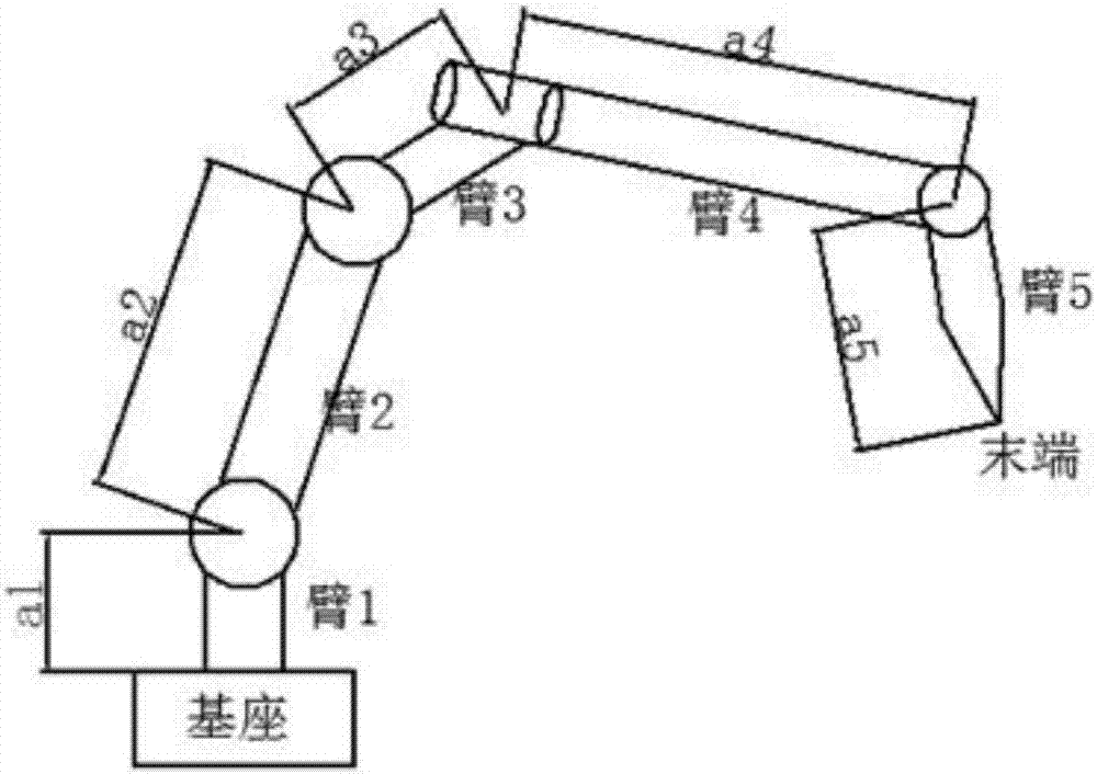
[0028] see Figure 1~2 , the method for robot accuracy calibration includes the following steps:

[0029] 1) Use CNC processing technology to process a rectangular box with a machining accuracy of 0.01mm. Carve coordinate points on the surface of the rectangular box, and use the intersection of any three sides of the box as the coordinate origin to establish a basic coordinate system. The robot is set in the basic coordinate system through the base, and encoders are installed at each joint of the robot. Each encoder is connected to the data acquisition card through the data bus. position in the coordinate system.

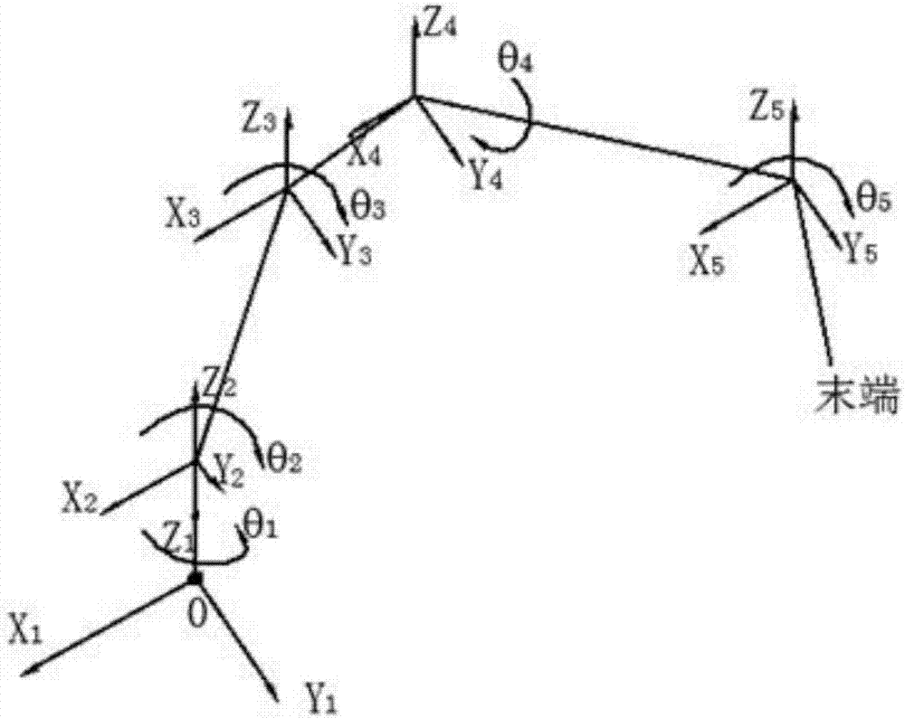
[0030] 2) Specify a theoretical reference coordinate system for each joint of the robot, and use the D-H notation to model the robot. The motion pose of each joint is determined by four kinematic parameters: the angle θ between adjacent links; The distance d between rods; the distance a between adjacent joints; the angle α between adjacent joint axes.

[0031] 3)...

Embodiment 2

[0054] The robot in this embodiment can have six axes or more, and the above method can also be used for calibration.

Embodiment 3

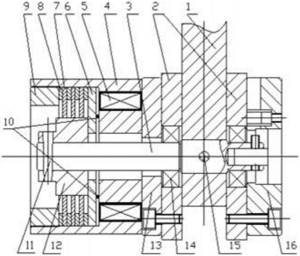
[0056] see image 3 , in order to further ensure the accuracy of robot precision calibration, this embodiment installs an electromagnetic clutch at the joint of the adjacent mechanical arm of the robot. The electromagnetic clutch includes a fixed arm 2, a rotating arm 1, a rotating shaft 3 and a clutch body, and the rotating arm 1. The cylindrical pin 15 is fixedly connected to the rotating shaft 3. The rotating shaft 3 and the fixed arm 2 are arranged to rotate relative to each other. The clutch body is connected between the fixed arm 2 and the rotating shaft 3 and controls the rotation and stop of the rotating shaft 3. Two adjacent The two mechanical arms are connected to the rotating arm 1 and the fixed arm 2 respectively, and the rotating shaft 3 is locked on the fixed arm 2 by using the clutch body, and then the rotating arm 1 is locked. The structure is simple, the operation is easy, the cost is low, and the precision of the robot is greatly improved. The two fixed arms ...


PUM


Abstract

The invention discloses a method for robot precision calibration. The method for robot precision calibration includes the following steps of building a fundamental coordinate system; assigning a theoretical reference coordinate system for each joint of a robot, conducting modeling on the robot through a D-H representation method; building a transformational matrix A<n+1> of every two adjacent joints, and obtaining a total transformation matrix T of the robot through the sequential right multiplication of the transformational matrixes; calculating a theoretical pose X of the tail end of the robot relative to the reference coordinate systems; building an error calculation equation (please see the specifications for the equation) of the robot, and obtaining delta X; and obtaining a parameter error delta P (please see the specifications for the formula) of the robot through a least square method, and the parameter error Pn=P<n-1>+delta P of each joint, and finally compensating the errors to D-H model parameters of the robot. The method for robot precision calibration is easy and convenient to operate and low in cost, and the precision of the robot is improved greatly.

Description

technical field [0001] The invention relates to the technical field of robots, in particular to a method for calibrating robot precision. Background technique [0002] Robot accuracy refers to repeat positioning accuracy and absolute positioning accuracy, which is mainly limited by robot processing and assembly accuracy. Accuracy calibration can correct its D-H parameters on the basis of this inherent property. At present, the calibration methods of industrial robots mainly include open-loop calibration (laser tracker, IGPS), calibration based on physical constraints, calibration based on vision and other methods, which have problems such as high measurement cost, limited processing accuracy, and conversion error. Contents of the invention [0003] The object of the present invention is to provide a method for robot precision calibration to solve the problem of poor calibration precision of existing robots, which is easy to operate, low in cost, and greatly improves robot ...

Claims


Application Information

Patent Timeline
IPC IPC(8): B25J9/04
CPCB25J9/046
Inventor 王荣军田伟超张晶赵静静关伟
Owner HORIZON MICROPORT MEDICAL TECH BEIJING CO LTD
Why Eureka
Try Eureka