Ultrasonic punching device for blast furnace slag

An ultrasonic and blast furnace slag technology, applied in the field of blast furnace slag ultrasonic punching device, can solve the problems of insufficient heat exchange speed, uneven particle size of water slag, increase equipment load, etc. The particle size of water slag and the effect of reducing equipment load

Active Publication Date: 2017-08-18
WUHAN UNIV OF SCI & TECH
View PDF3 Cites 1 Cited by
  • Summary
  • Abstract
  • Description
  • Claims
  • Application Information

AI Technical Summary

Problems solved by technology

The water slag in the ordinary water slag flushing device cannot be fully combined, resulting in uneven particle size of the water slag, which affects its performance; at the same time, the heat exchange rate during the slag flushing process is not fast enough, which increases the load on the equipment; the acid waste gas generated during the flushing process will cause equipment erosion and pollute the environment

Method used


Image

  • Ultrasonic punching device for blast furnace slag
  • Ultrasonic punching device for blast furnace slag
  • Ultrasonic punching device for blast furnace slag

Examples


Embodiment Construction

[0018] The present invention will be further described below in conjunction with the accompanying drawings.

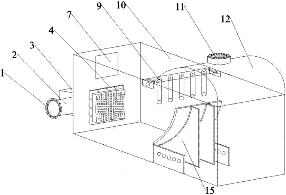
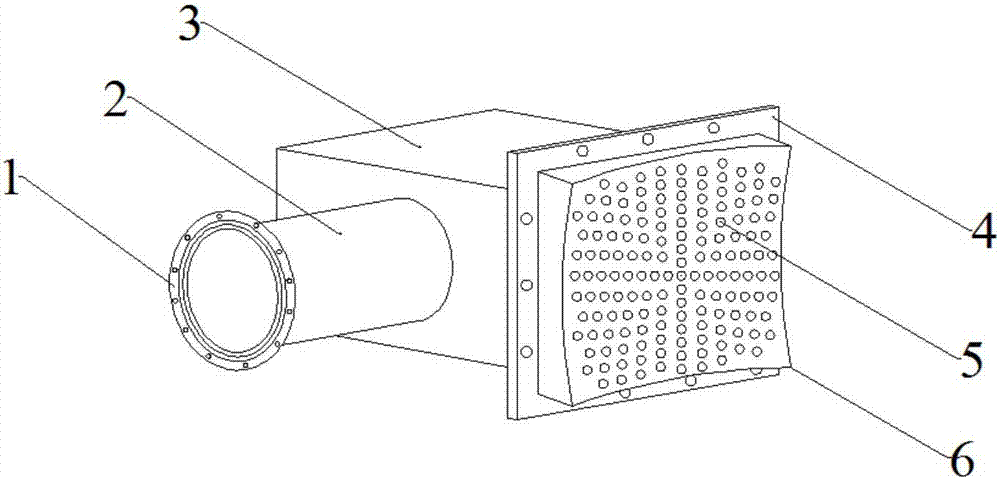
[0019] refer to figure 1 , 2 , The main body 3 of the flushing tank is installed below the slag inlet 7. There is a water inlet pipe 2 on one side of the main body of the water tank. The water inlet pipe 2 is connected to the external water pipe through the flange disc 1 to save floor space and reduce space occupation.

[0020] The main body of the flushing tank is connected with the punching orifice plate 6 through the flange plate 4. There is a punching nozzle 5 on the punching orifice plate 6. Evenly distributed in the radial direction to achieve the effect of converging the slag flushing stream and enhancing the punching efficiency.

[0021] A slag flushing ditch 16 is formed between the left and right retaining walls 10 of the main body of the flushing device; the first half of the slag flushing ditch is an inclined section, and the second half is a gentle secti...


PUM


Abstract

The invention relates to an ultrasonic punching device for blast furnace slag. A flushing tank body is located below a slag inlet. A water tank body is provided with a water inlet pipe, and the water inlet pipe is connected with an externally-connected water pipe. The flushing tank body is connected with a punching pore plate with punching nozzles. A slag flushing ditch is formed between a left-side retaining wall and a right-side retaining wall. The slag flushing ditch is provided with an inclined section and a gentle section. A cambered surface top covering plate is arranged on the rear section of a punching device body. A waste gas collection device is arranged on the cambered surface top covering plate. Amplitude-change poles of an ultrasonic generation device are connected to the left-side retaining wall and the right-side retaining wall. A flow distribution device is mounted on the gentle section of the slag flushing ditch. Flow distribution partitions are arranged on an arc-shaped baffle of the flow distribution device. By means of the ultrasonic punching device for the blast furnace slag, the blast furnace slag enters the slag flushing ditch from the slag inlet, flushing water enters the slag flushing ditch from the punching nozzles in a gathered manner, the flow distribution of the water granulated slag stream is conducted through the flow distribution device and the ultrasonic generation device, and the generation of foaming slag is inhibited; and the granularity of the water granulated slag is uniformized, harmful gas such as SOx and H2S is absorbed effectively, and waste gas is collected and treated by a waste collection device and then discharged. The ultrasonic punching device is simple in structure and environmentally friendly.

Description

technical field [0001] The invention relates to the technical field of blast furnace slag processing devices, in particular to a blast furnace slag ultrasonic punching device. Background technique [0002] With the development of the ironmaking process, the slag produced in the ironmaking process has been widely used. At present, most of the blast furnace slag in my country adopts water treatment methods, and the commonly used water treatment methods include INBA method, Lhasa method, foaming slag method, Minter method and so on. The blast furnace slag obtained from water treatment has excellent value, it has potential hydraulic gelling properties, and can be used to make slag cement; it can also be used to make slag bricks and slag concrete products; it can also be used for thermal insulation fillers; Slag powder is produced by ultra-fine grinding. Water flushing slag process is the initial process of slag treatment, which has an important impact on the performance of wat...

Claims


Application Information

Patent Timeline
Patent Type & Authority Applications(China)
IPC IPC(8): C21B3/08C21B3/06
CPCC21B3/06C21B3/08C21B2200/00Y02W30/50
Inventor 金焱罗霄叶格凡朱雯王俊刘文鹏
Owner WUHAN UNIV OF SCI & TECH
Why Eureka
Try Eureka