Automatic quenching machine

A quenching machine and automatic technology, applied in the direction of quenching device, furnace type, furnace, etc., can solve the problems of high labor intensity, difficult adjustment of pipe fittings, and easy safety accidents, so as to reduce labor intensity and personal safety, ensure position accuracy, The effect of reducing scrap rate

Active Publication Date: 2017-08-18
东莞乌佩克自动化工程技术有限公司
View PDF12 Cites 5 Cited by
  • Summary
  • Abstract
  • Description
  • Claims
  • Application Information

AI Technical Summary

Problems solved by technology

This method is easy to cause bending and deformation of the pipe fittings, which affects the processing accuracy of the pipe fittings. It is difficult to correct the deformation error of the pipe fittings after quenching. It can only be leveled by manual beating, and manual beating is time-consuming and laborious. The beating process also produces large noise pollution. The beating method also directly affects the appearance quality of the product, and even produces internal stress, which is prone to breakage during use, making the pipe fittings unusable; and the box furnace is used for manual quenching, and the pipe fittings are manually clamped and immersed in the quenching water pool for quenching
This artificial quenching method has slow transfer time, high labor intensity and low work efficiency, and under long-term high temperature conditions, the clamps need to be replaced frequently, which increases the maintenance cost
In addition, due to the high quenching temperature of pipe fittings, safety accidents are prone to occur

Method used


Image

  • Automatic quenching machine
  • Automatic quenching machine
  • Automatic quenching machine

Examples


Embodiment Construction

[0036] In order to facilitate the understanding of those skilled in the art, the present invention will be further described below with reference to the embodiments and the accompanying drawings, and the contents mentioned in the embodiments are not intended to limit the present invention.

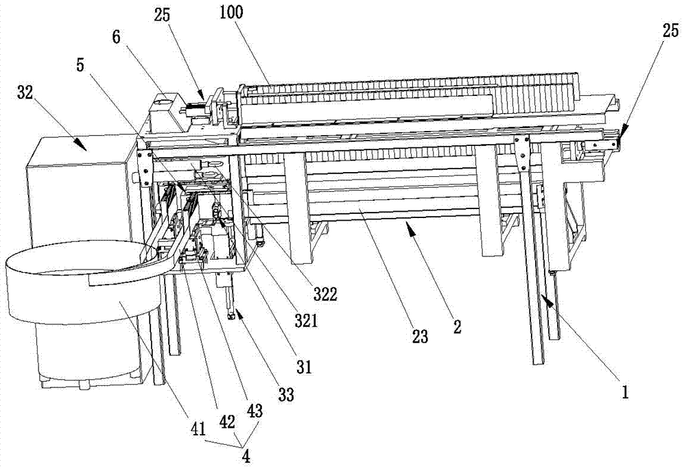
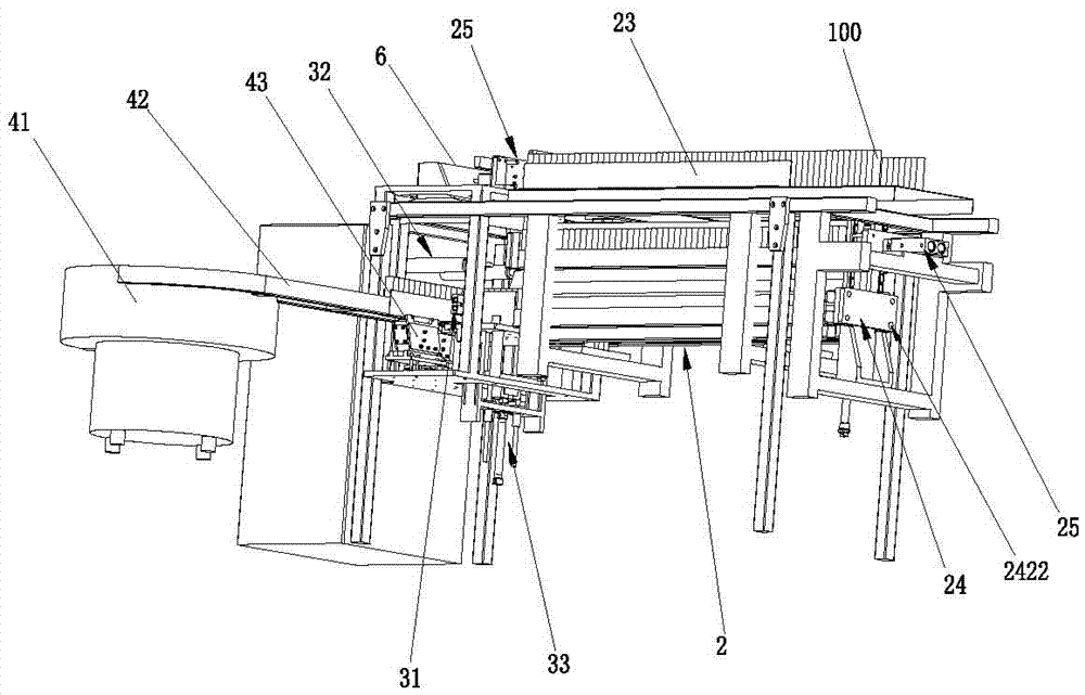
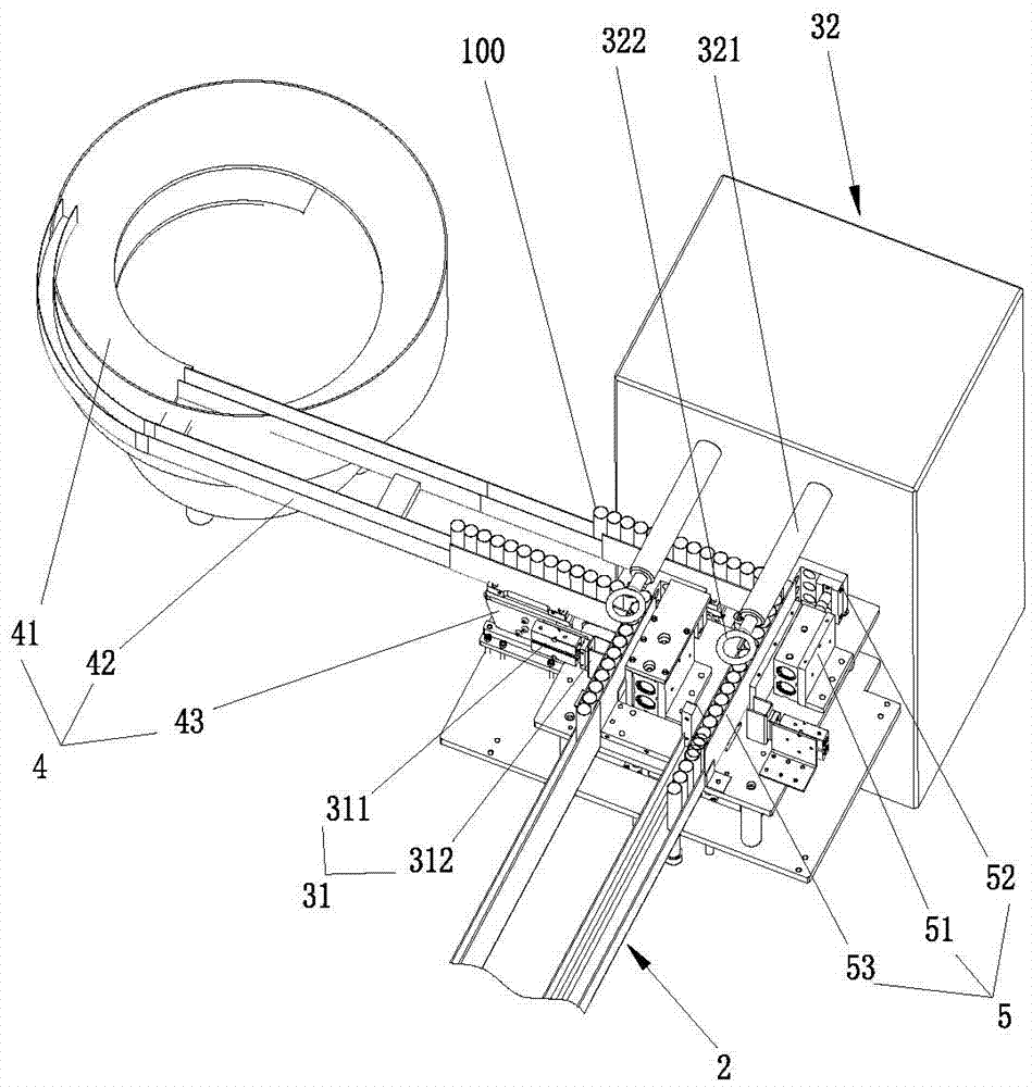
[0037] like Figure 1 to Figure 10 As shown in the figure, an automatic quenching machine provided by the present invention includes a frame 1, a feeding device 4, a first pushing mechanism 5 arranged at the discharge end of the feeding device 4, and is used for removing the materials in the first pushing mechanism 5. The material positioning mechanism 31 for positioning, the material lifting mechanism 33 for lifting the positioned material, the heating device 32 for heating the lifted material, and the cooling device 2 for cooling the heated material, said The cooling device 2 is installed on the rack 1, and the discharge end of the first pushing mechanism 5 is communicated with the feed ...


PUM


Abstract

The invention relates to the technical field of quenching equipment, in particular to an automatic quenching machine. The automatic quenching machine comprises a rack, a feeding device, a first material pushing mechanism arranged at the discharging end of the feeding device, a material positioning mechanism for positioning of materials in the first material pushing mechanism, a material lifting mechanism for rising and falling of the positioned materials, a heating device for heating the lifted materials and a cooling device for cooling the heated materials. The cooling device is mounted on the rack, and the discharging end of the first material pushing mechanism communicates with the feeding end of the cooling device. According to the automatic quenching machine, automatic feeding, positioning, heating, cooling and outputting of pipe pieces are achieved, quenching efficiency of the pipe pieces is improved, the labor intensity of workers is relieved, the personal safety of the workers is improved, the position accuracy of the pipe pieces is ensured, the quenching quality of the pipe pieces is improved, the rejection rate of the quenched pipe pieces is decreased, and production cost is reduced.

Description

technical field [0001] The invention relates to the technical field of quenching equipment, in particular to an automatic quenching machine. Background technique [0002] The existing quenching method for pipe fittings is: heating the pipe fittings to a specified temperature, and directly cooling them in water or oil. This method is easy to cause the bending deformation of the pipe fittings, which affects the machining accuracy of the pipe fittings. The deformation error of the pipe fittings after quenching is difficult to correct, and can only be leveled by manual beating. Manual beating is time-consuming and laborious, and the beating process also produces large noise pollution. The beating method also directly affects the appearance quality of the product, and even generates internal stress, which is easy to break during use, making the pipe fittings unusable; and the box furnace is used for manual quenching, and the pipe fittings are manually clamped and immersed in the ...

Claims


Application Information

Patent Timeline
Patent Type & Authority Applications(China)
IPC IPC(8): C21D9/08C21D1/62
CPCC21D1/62C21D9/085Y02P10/20
Inventor 刘步良刘步凯
Owner 东莞乌佩克自动化工程技术有限公司
Why Eureka
Try Eureka