
Hydraulic control system for automatic gearbox

A technology of hydraulic control system and automatic transmission, applied in transmission control, components with teeth, belts/chains/gears, etc., which can solve the problems that automatic transmissions cannot be entered, gears cannot be interlocked, and vehicles cannot be moved. , to improve the efficiency of the transmission, reduce the power consumption of the oil pump, and achieve the effect of compact layout

Pending Publication Date: 2017-08-18
SHAANXI FAST GEAR CO
View PDF7 Cites 17 Cited by
  • Summary
  • Abstract
  • Description
  • Claims
  • Application Information

AI Technical Summary

Problems solved by technology

The control of the shift actuator is generally controlled one-to-one. This control method is simple, but the interlocking between the gears cannot be realized, and when the power failure occurs, the automatic transmission cannot enter the appropriate gear, causing the vehicle unable to move

Method used


Image

  • Hydraulic control system for automatic gearbox
  • Hydraulic control system for automatic gearbox
  • Hydraulic control system for automatic gearbox

Examples


Embodiment Construction

[0029] The present invention is described in further detail below in conjunction with accompanying drawing:

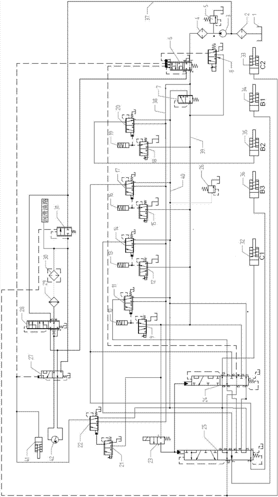
[0030] see figure 1 , The hydraulic control system of the automatic transmission of the present invention is composed of three parts of the oil circuit, which are respectively the oil supply oil circuit, the shift control oil circuit, the torque converter and the cooling lubricating oil circuit.

[0031] The oil supply route consists of an oil tank 1, a first filter 2, a second filter 4, an oil pump 3, an overflow valve 5, a system pressure regulating valve 6, a proportional solenoid valve 8 and a recirculation oil circuit 37. The first filter 2 is installed between the oil pump and the oil tank, which can remove large-sized pollutants in the oil tank, and the second filter 4 is installed behind the high-pressure oil outlet of the oil pump to ensure that the oil entering the shift control oil circuit Reach the cleanliness required by the hydraulic system. The oil thr...


PUM


Abstract

The invention discloses a hydraulic control system for an automatic gearbox. The hydraulic control system for an automatic gearbox comprises three oil path parts of an oil supply path, a gear shifting control oil path, a toque converter and a cooling lubricating oil path. An input end of the oil supply path is connected to an oil groove, and oil liquid is output to the gear shifting control oil path, the torque converter and the cooling lubricating oil path. The hydraulic control system for an automatic gearbox realizes control over respective gears of a six-gear automatic gearbox, and the oil liquid output by liquid control proportional valves controlled by proportional solenoid valves will not control a clutch or a brake directly, but enters a C1 interlocking valve and a C2 interlocking valve at first. The oil liquid is then output to the corresponding clutch / brake by different oil mouths of the two interlocking valves and different working positions, interlocking among respective gears is realized, and when power loss occurs, a hydraulic system will automatically select a proper gear to continue to work according to the current gear, an automobile can be rapidly driven away from a hazardous area and finished automobile safety is improved.

Description

[0001] 【Technical field】 [0002] The invention belongs to the technical field of transmissions, and relates to a hydraulic control system of an automatic transmission. [0003] 【Background technique】 [0004] The control of the automatic transmission is mainly realized through the hydraulic system. Among them, the control of the main oil pressure of the system is related to the efficiency of the transmission; the control of the shift actuator is closely related to the comfort and safety of the vehicle. The control of the main oil pressure is generally adjusted by its own feedback and the feedback oil circuit of the relevant clutch at home and abroad, but this adjustment is passive, and the pressure adjustment range is very limited. The control of the shift actuator is generally controlled one-to-one. This control method is simple, but the interlocking between the gears cannot be realized, and when the power failure occurs, the automatic transmission cannot enter the appropria...

Claims


Application Information

Patent Timeline
Patent Type & Authority Applications(China)
IPC IPC(8): F16H61/00
CPCF16H61/0003F16H61/0009F16H61/0025F16H2061/0037
Inventor 邱辉鹏张海涛彭立印周能文林勇王凯峰许国界葛敬广王亚峰刘义
Owner SHAANXI FAST GEAR CO
Learn More