
Refrigerator freezer and its drawer assembly

A technology for refrigerating and freezing devices and drawers, which is applied to household refrigeration devices, cooling fluid circulation devices, coolers, etc., can solve the problems of difficult control, high cost, and complicated operation, and achieves simple and ingenious structure, improved user experience, and convenient operation. Effect

Active Publication Date: 2019-05-31
HAIER SMART HOME CO LTD
View PDF4 Cites 0 Cited by
  • Summary
  • Abstract
  • Description
  • Claims
  • Application Information

AI Technical Summary

Problems solved by technology

[0003] For this reason, the existing refrigerating and freezing devices are equipped with complex mechanical or electromagnetic locking mechanisms to lock the drawer and the cylinder body, but the existing locking mechanisms have complex structures and are difficult to manufacture, or the operation is cumbersome and difficult to control, or the cost is relatively high
In addition, some locking mechanisms based on electromagnetic or electric principles cannot open the drawer normally when the power is off, which brings a lot of inconvenience to users.

Method used


Image

  • Refrigerator freezer and its drawer assembly
  • Refrigerator freezer and its drawer assembly
  • Refrigerator freezer and its drawer assembly

Examples


Embodiment Construction

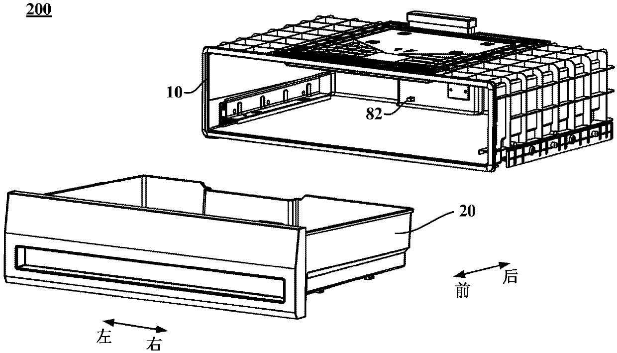
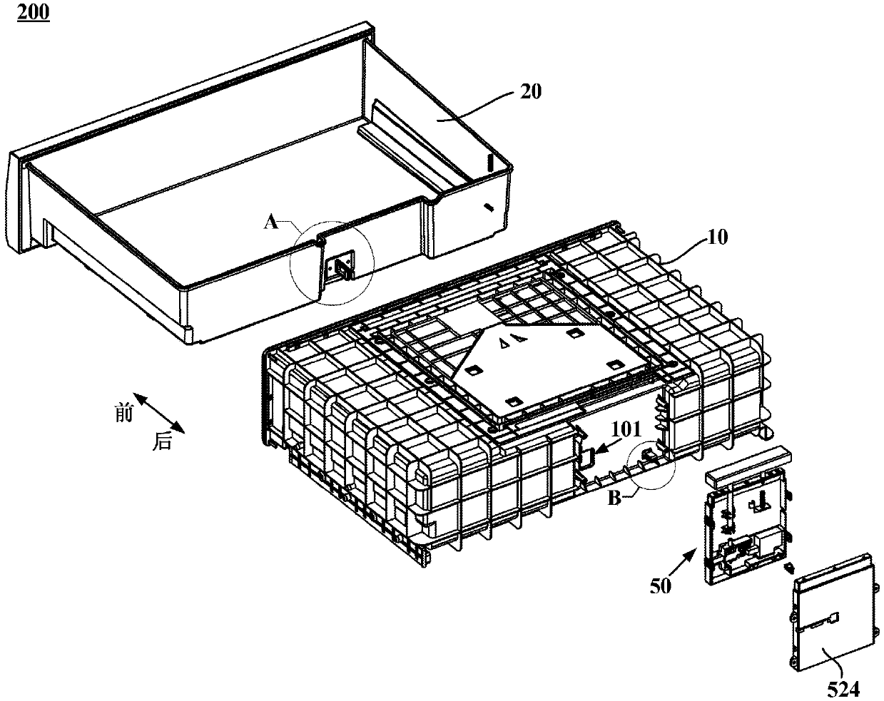
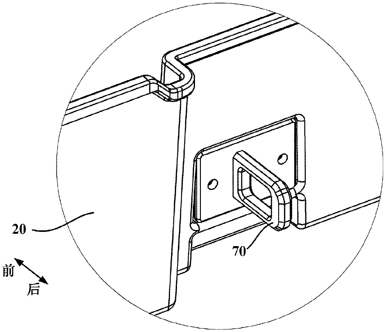
[0047] figure 1 is an exploded schematic diagram of a drawer assembly according to an embodiment of the present invention; figure 2 Yes figure 1 An exploded schematic view of another view of the drawer assembly shown. like figure 1 and figure 2 As shown, an embodiment of the present invention provides a drawer assembly 200 for a refrigerating and freezing device (such as a refrigerator). The drawer assembly 200 includes a cylindrical body 10 with an open front side, a drawer 20 that can be inserted into the cylindrical body 10 in a front-rear push-pull manner, and an electric Locking mechanism 50 . The cylindrical body 10 can be detachably mounted on the refrigerating and freezing device, or the cylindrical body 10 can be directly formed from the compartment of the refrigerating and freezing device, that is, a drawer-type compartment is formed. After the drawer 20 is completely inserted into the barrel 10 , the electronically controlled locking mechanism 50 is used to l...


PUM


Abstract

The invention relates to a refrigeration and freezing device and a drawer assembly of the refrigeration and freezing device. The drawer assembly comprises a barrel body with the opened front side, a drawer capable of being inserted into the barrel body in a front-back pushed-pulled mode, and an electric control lock mechanism. The electric control lock mechanism comprises a clamping ring, an electric control lock and an emergency unlocking rod. The clamping ring is arranged on the rear wall of the outer side of the drawer. When the drawer is completely pushed into the barrel body, the clamping ring stretches out of the barrel body through a through hole in the rear wall of the barrel body. The electric control lock is configured to be controlled to enable a lock pin of the electric control lock to horizontally move back and forth in the transverse direction so as to be inserted into or disengaged from the clamping ring, and therefore the drawer is locked to or unlocked from the barrel body. The lock pin is provided with a first inclined face which is gradually inclined in the direction away from the clamping ring from bottom to top. The emergency unlocking rod is arranged above the lock pin in a vertical extending mode. The lower end of the emergency unlocking rod is provided with a second inclined face parallel to the first inclined face. According to the configuration, when the lock pin is inserted into the clamping ring, in the moving-down process of the emergency unlocking rod, the lock pin is pushed through cooperation of the second inclined face and the first inclined face to be disengaged from the clamping ring. Automatic locking and unlocking can be achieved for the drawer and the barrel body, convenience is brought to users for operation, and the drawer can still be unlocked when the electric control lock mechanism loses efficacy.

Description

technical field [0001] The invention relates to a refrigeration device, in particular to a refrigerating and freezing device and a drawer assembly thereof. Background technique [0002] The drawer of the refrigerating and freezing device is generally arranged in a cylinder in a push-pull manner. With the increasing demand for food preservation, it is necessary to form a good seal between the front panel of the drawer and the opening of the cylinder after the drawer is completely pushed into the cylinder, that is, the front panel needs to be close to the opening of the cylinder. [0003] For this reason, the existing refrigerating and freezing device is provided with a complex mechanical or electromagnetic locking mechanism to lock the drawer and the cylinder, but the existing locking mechanism or structure is complicated and difficult to manufacture, or the operation is cumbersome and difficult to control, or the cost is high . In addition, some locking mechanisms based on...

Claims


Application Information

Patent Timeline
Patent Type & Authority Patents(China)
IPC IPC(8): F25D11/02F25D25/02F25D17/06
CPCF25D11/02F25D17/062F25D25/025
Inventor 王晶朱小兵张浩刘磊
Owner HAIER SMART HOME CO LTD
Learn More