Array type parallel laser projection three-dimensional scanning method

A technology of laser projection and three-dimensional scanning, applied in the direction of using optical devices, measuring devices, instruments, etc., can solve the problems of discrete projection pixels, affecting the accuracy of three-dimensional scanning, nonlinearity of light intensity, etc.

Active Publication Date: 2017-08-18
XIAN CHISHINE OPTOELECTRONICS TECH CO LTD
View PDF9 Cites 42 Cited by
  • Summary
  • Abstract
  • Description
  • Claims
  • Application Information

AI Technical Summary

Problems solved by technology

However, in the traditional laser line scanning measurement method, one or more light knives are projected in one direction to the measured object. Since the laser line width is usually 0.2mm-0.5mm, it is difficult to compress physically. When the measured object has When the edges are perpendicular to each other, the traditional measurement method can only measure the edge in a certain direction to meet the requirements. When using the traditional measurement method, multiple measurements are required and a rotating device is required
At the same time, the measurement accuracy of traditional laser scanning will be affected by light source technology and projection equipment. Traditional projection lenses use digital light technologies such as DLP and LCD, but due to discrete projection pixels, limited resolution, nonlinear light intensity and power consumption High disadvantages seriously affect the accuracy of 3D scanning

Method used


Image

  • Array type parallel laser projection three-dimensional scanning method
  • Array type parallel laser projection three-dimensional scanning method
  • Array type parallel laser projection three-dimensional scanning method

Examples


Embodiment Construction

[0024] The present invention will be described in detail below in conjunction with the accompanying drawings.

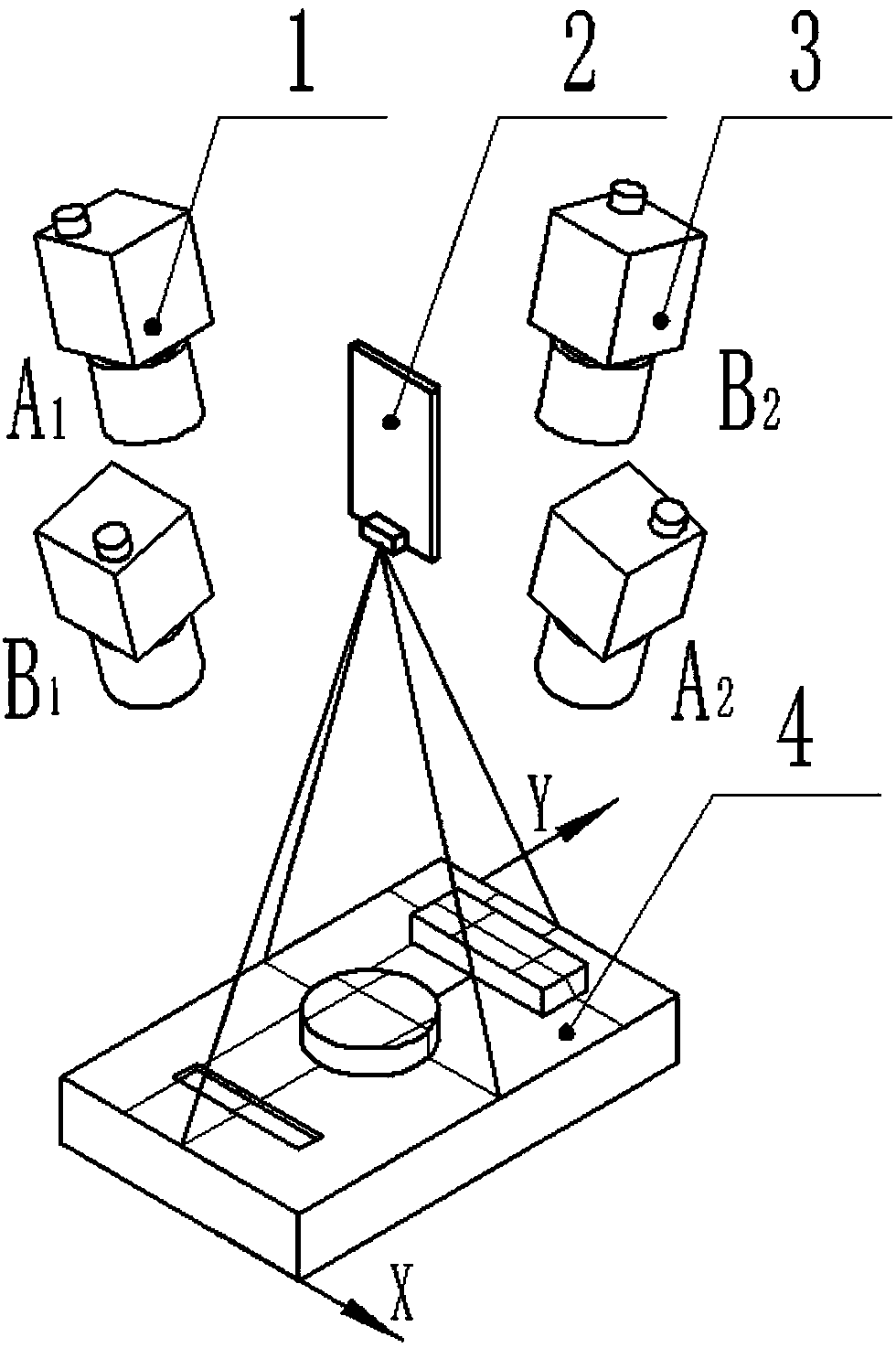
[0025] An array parallel laser projection three-dimensional scanning device ( Figure 1 As shown), it includes a laser micro-mirror projection device for projecting laser light in different directions and two or more array cameras for data acquisition, and the cameras are distributed in an array around the laser projection device.

[0026] An arrayed parallel laser projection three-dimensional scanning system specifically includes the following steps:

[0027] The first step is to calibrate the system parameters.

[0028] Before scanning the measured object, calibrate the internal parameters of the camera and the pose relationship between the camera and the laser plane. In this step, a group of monocular systems and a group of binocular systems are taken as examples to introduce the specific calibration process.

[0029] (1) Calibrate the internal and external par...


PUM


Abstract

The invention discloses an array type parallel laser projection three-dimensional scanning method. The array type parallel laser projection three-dimensional scanning method comprises steps that a laser micro-vibration mirror projection device used for projecting line lasers in different directions and a plurality of array type cameras used for data acquisition are provided; laser cutter separation of each acquired image in different directions is carried out, and the laser cutter centers of the laser cutters in various directions are respectively extracted, and according to a triangle relation among the projection device and the cameras, an object surface three-dimensional coordinate of a line laser position is acquired; the projection device is used to move the line laser on the object surface by one pixel each time, and the above mentioned process of extracting the object three-dimensional coordinate on the laser cutter position is repeated until the three-dimensional coordinate of the whole object surface is acquired by the laser cutter. The laser projection device adopts MEMS scanning vibration mirror laser, and compared with a digital light and physical grating technology, field depth is large, scanning speed is fast, a size is small, and scanning precision is high; and at the same time, the system is used to distribute the cameras in an array, and then the sensitivity to complicated step edge measurement is provided, and then the non-contact, high-speed, and object edge step high precision measurement of the object is realized.

Description

technical field [0001] The invention belongs to the field of optical three-dimensional measurement. Multiple cameras are distributed in an array and laser projection devices are combined into an array parallel laser projection three-dimensional scanning system. The system is sensitive to complex step edge measurement and can realize non-contact, high-speed and object detection of objects Edge steps are measured with high precision. Background technique [0002] Due to the advantages of non-contact, high precision and high speed, optical three-dimensional measurement has emerged in industries such as industrial manufacturing, animation special effects production, game entertainment and medicine, showing huge technological advancement and strong vitality, and its application is in the ascendant , and manufacturers are gradually developing products with better performance, and a large-scale industry has initially formed. [0003] There are two types of optical three-dimensiona...

Claims


Application Information

Patent Timeline
Patent Type & Authority Applications(China)
IPC IPC(8): G01B11/25
CPCG01B11/2513
Inventor 周翔李东李欢欢王超
Owner XIAN CHISHINE OPTOELECTRONICS TECH CO LTD
Why Eureka
Try Eureka