Infrared transmitting device and infrared receiving device of atmospheric infrared detection equipment

A technology of infrared detection and infrared emission, which is applied in measuring devices, optical testing of flaws/defects, material analysis through optical means, etc. It can solve the problem of difficult adjustment of the sending and receiving ends of infrared beams, insufficient adjustment accuracy, poor stability, etc. problems, to achieve the effect of improving equipment assembly and maintenance efficiency, high adjustment accuracy and good stability

Pending Publication Date: 2017-08-18
安徽星源环境科技有限公司
View PDF3 Cites 12 Cited by
  • Summary
  • Abstract
  • Description
  • Claims
  • Application Information

AI Technical Summary

Problems solved by technology

In the stage of equipment alignment, if the stability of the equipment is poor or the adjustment accuracy is not enough, it will be difficult to correctly adjust the receiving end of the infrared beam in place

Method used


Image

  • Infrared transmitting device and infrared receiving device of atmospheric infrared detection equipment
  • Infrared transmitting device and infrared receiving device of atmospheric infrared detection equipment
  • Infrared transmitting device and infrared receiving device of atmospheric infrared detection equipment

Examples


Embodiment 1

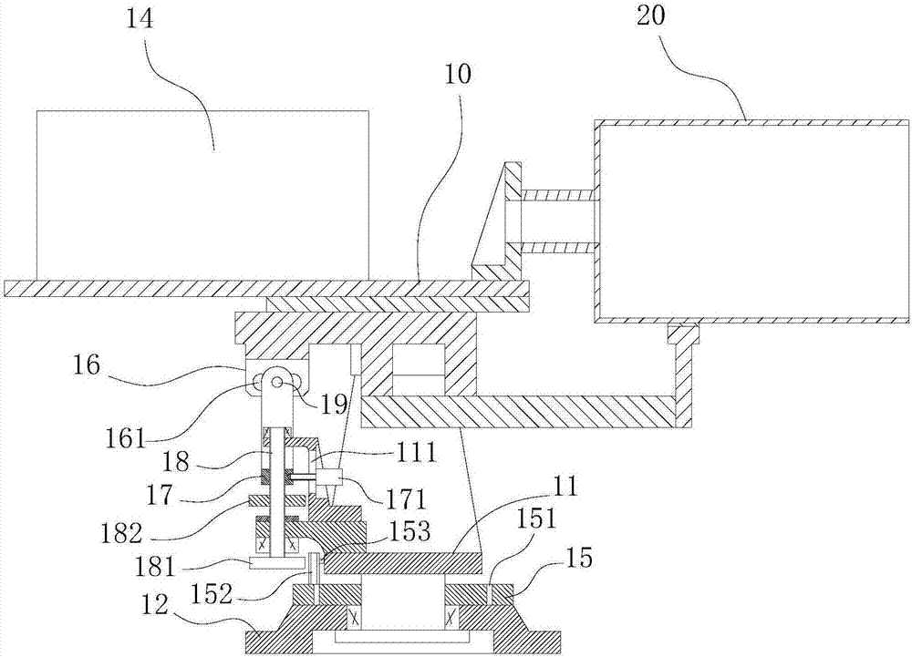
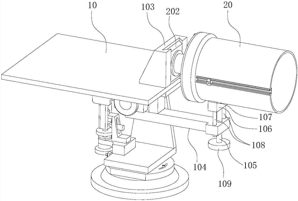
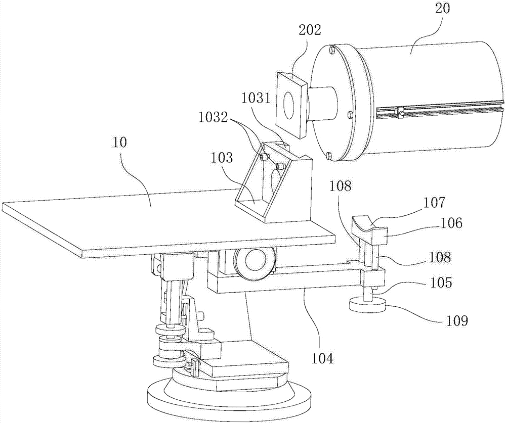
[0024] Such as Figure 1-10 As shown, an infrared emitting device of an atmospheric infrared detection device includes an infrared light source 14 and a Karl's reflective telescope 20, and the infrared beam emitted by the infrared light source 14 is projected after being expanded by the Karl's reflective telescope 20; the infrared light source 14 and Karl's reflective telescope 20 are installed on a turntable 10, said turntable 10 comprises supporting plate 10, support 11 and base 12, said supporting plate 10 is used for installing infrared light source 14 and Karl's reflecting telescope 20, said supporting plate 10 is rotatably arranged on the support 11 along the horizontal direction perpendicular to the axis of the Karl's reflecting telescope 20 to realize the pitch adjustment of the Karl's reflecting telescope 20, and the support 11 is arranged on the base 12 by rotating along the vertical axis to realize Karl's The left and right adjustment of the reflecting telescope 20;...

Embodiment 2

[0031] An infrared receiving device of an atmospheric infrared detection device, comprising an interferometer, an infrared detector, and all structures except the infrared light source 14 in the infrared emitting device of the atmospheric infrared detection device described in Embodiment 1, the interferometer and the infrared detection device The reflector is installed on the support plate 10, and the Karl's reflecting telescope 20 is used to receive the infrared beam, focus the infrared beam and inject it into the interferometer, and the infrared beam is modulated by the interferometer and then injects into the infrared detector.


PUM


Abstract

The invention belongs to the technical field of atmospheric infrared detection equipment, and particularly relates to an infrared transmitting device and an infrared receiving device of the atmospheric infrared detection equipment. The overall pitching and left and right sweeping of the infrared detection equipment are achieved through a two-axis turntable. The equipment is simple in transmission structure, good in stability and high in adjustment precision, thus the installation and focusing efficiency and focusing precision of the infrared detection equipment are greatly improved. According to the equipment, a lens is installed on a movable support; the movable support is installed on a slider arranged on the barrel wall of a Casher reflection telescope; the position of the lens in the Casher reflection telescope can be adjusted in real time from the outside of the Casher reflection telescope; the operation is simple and convenient; the equipment assembly and maintenance efficiency are improved; the fast connection and positioning of the Casher reflection telescope and the turntable are achieved by using a dovetail type plug-in structure; the connecting structure is stable and reliable; the installation precision is high.

Description

technical field [0001] The invention belongs to the technical field of atmospheric infrared detection equipment, and in particular relates to an infrared emitting device and an infrared receiving device of atmospheric infrared detection equipment. Background technique [0002] Air pollution is one of the major problems currently facing our country. Continuous online monitoring of ambient air, mastering the emission, diffusion and evolution of pollutant gases, and realizing accurate traceability are of great significance for formulating emission reduction policies, evaluating emission reduction programs, and thoroughly solving air pollution problems. important meaning. Using the "infrared fingerprint" absorption characteristics of the gas to be measured for spectral quantitative analysis to obtain the concentration of the gas to be measured has an important application in the field of online gas detection. Gas concentration detection based on infrared spectroscopy can be div...

Claims


Application Information

Patent Timeline
Patent Type & Authority Applications(China)
IPC IPC(8): G01N21/01G01N21/94G01N21/3504
CPCG01N21/01G01N21/3504G01N21/94
Inventor 唐宗佳樊汇川
Owner 安徽星源环境科技有限公司
Why Eureka
Try Eureka