Multi-channel optical transceiver module

A multi-channel, optical transceiver technology, applied in the field of optical communication systems, can solve the problems of actual manufacturing troubles, many variable parameters, and low efficiency, and achieve the effects of stable and reliable transmission paths, flexible switching and scheduling, and low cost

Active Publication Date: 2017-08-18
WUHAN POWERISE OPTOELECTRONICSAL TECH
View PDF5 Cites 28 Cited by
  • Summary
  • Abstract
  • Description
  • Claims
  • Application Information

AI Technical Summary

Problems solved by technology

Or conversely, the laser driver LDD 250 drives the laser 240 with four wavelengths to emit light wave signals, which are coupled into the waveguide corresponding to the AWG 220 by the focusing lens 230, and then coupled into the fiber adapter 205 by the lens 210 after being combined by the AWG. The aforementioned TFF-type WDM demultiplexer has a high degree of integration, but the fiber optic adapter 205, the focusing lens 210, the AWG 220, the focusing lens (or focusing lens array) 230 and the PD (or PD array) need linkage adjustment, which can be Too many variable parameters lead to low efficiency, which brings great trouble and difficulty to actual manufacturing

Method used


Image

  • Multi-channel optical transceiver module
  • Multi-channel optical transceiver module
  • Multi-channel optical transceiver module

Examples


Embodiment Construction

[0041] The principles and features of the present invention are described below in conjunction with the accompanying drawings, and the examples given are only used to explain the present invention, and are not intended to limit the scope of the present invention.

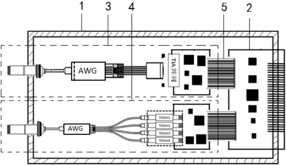
[0042] Such as image 3 As shown, a multi-channel optical transceiver integrated module includes a package 1, an assembled printed circuit board PCBA 2, a light receiving component 3 and a light emitting component 4, and the light receiving component 3 and the light transmitting component 4 are all arranged on the tube shell 1, the light-receiving component 3 and the light-emitting component 4 are respectively electrically connected to the PCBA 2 through a flexible circuit board 5, and one end of the light-receiving component 3 and the light-emitting component 4 both protrude from one end of the tube case 1 And connected with the external optical path, the PCBA2 protrudes from the other end of the tube case 1 and is...


PUM


Abstract

The invention relates to a multi-channel optical transceiver module comprising a tubular shell, a PCBA, an optical receiving component, and an optical transmitting component. Both the optical receiving component and the optical transmitting component are arranged in the tubular shell. The optical receiving component and the optical transmitting component are electrically connected with the PCBA through flexible circuit boards. One end of the optical receiving component and one end of the optical transmitting component extend out of one end of the tubular shell, and are connected with an external optical path. The PCBA extends out of the other end of the tubular shell, and is electrically connected with an external circuit. The problem that the existing optical path is of poor stability and is difficult to manufacture is solved. An optical fiber array and an optical multiplexing device are coupled together. The module has multiple wavelength channels. The transmission path of light beams is more stable and reliable. The module is more convenient and simple to produce and manufacture. The device is of higher reliability and lower cost.

Description

technical field [0001] The invention relates to the technical field of optical communication systems, in particular to a multi-channel optical transceiver integrated module. Background technique [0002] With the increasingly higher requirements for communication bandwidth in the field of optical fiber communication, global optical communication is currently in a period of rapid development. In the field of high-speed data communication, due to the speed bottleneck of electrical transmission, for the optical fiber communication network with a transmission rate requirement of 40 / 100Gbps, in order to ensure long-distance high-speed transmission of data, optical modules (optical transmission modules) are usually used in the prior art and optical receiving module) to realize the transmission and reception of light of different wavelengths. The commonly used solution is to multiplex 4 channels of optical signals of different wavelengths into a single-mode optical fiber for transm...

Claims


Application Information

Patent Timeline
Patent Type & Authority Applications(China)
IPC IPC(8): G02B6/42
CPCG02B6/428G02B6/4287G02B6/4296
Inventor 江永胜陈思乡李志远张平化陈昊生周火焱
Owner WUHAN POWERISE OPTOELECTRONICSAL TECH
Why Eureka
Try Eureka