Supercharge Your Innovation With Domain-Expert AI Agents!

A method of fabricating an optical fiber collimator array

An optical fiber collimator and manufacturing method technology, applied in the field of optical communication, can solve the problems of short working distance, assembly process requirements, array lens process limitations, etc., and achieve accelerated curing rate, adjustable working distance, and strong operability. Effect

Active Publication Date: 2019-04-12
THE 23RD RES INST OF CHINA ELECTRONICS TECH GRP CORP
View PDF6 Cites 0 Cited by
  • Summary
  • Abstract
  • Description
  • Claims
  • Application Information

AI Technical Summary

Problems solved by technology

In the first method, in order to ensure that the beams are parallel to each other, the spacing tolerance between the array optical fibers and the spacing tolerance between the array lenses must reach the order of microns, which requires high processing accuracy of the material components, making the material processing Complex, relatively high cost, and limited by the process of the array lens, the generally made fiber collimator array has a short working distance
Although the second method reduces the processing accuracy requirements for material components, since the collimators are fixed separately, it is difficult to avoid the position shift of some collimators during the manufacturing process or the stress release process in the later stage. The craftsmanship has high requirements, and the problem of short working distance has not been well solved

Method used


Image

  • A method of fabricating an optical fiber collimator array
  • A method of fabricating an optical fiber collimator array
  • A method of fabricating an optical fiber collimator array

Examples


Embodiment Construction

[0025] The present invention will be further described in detail below in conjunction with the accompanying drawings and embodiments.

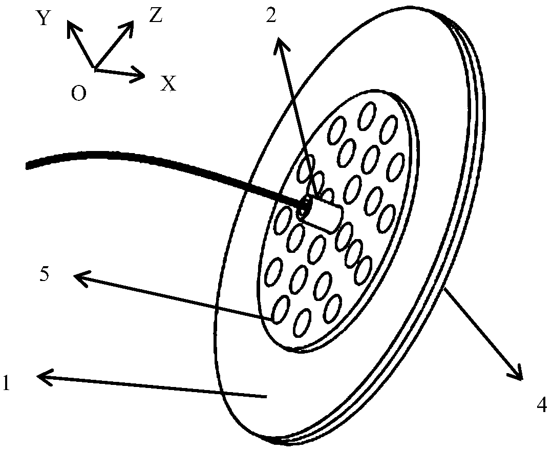
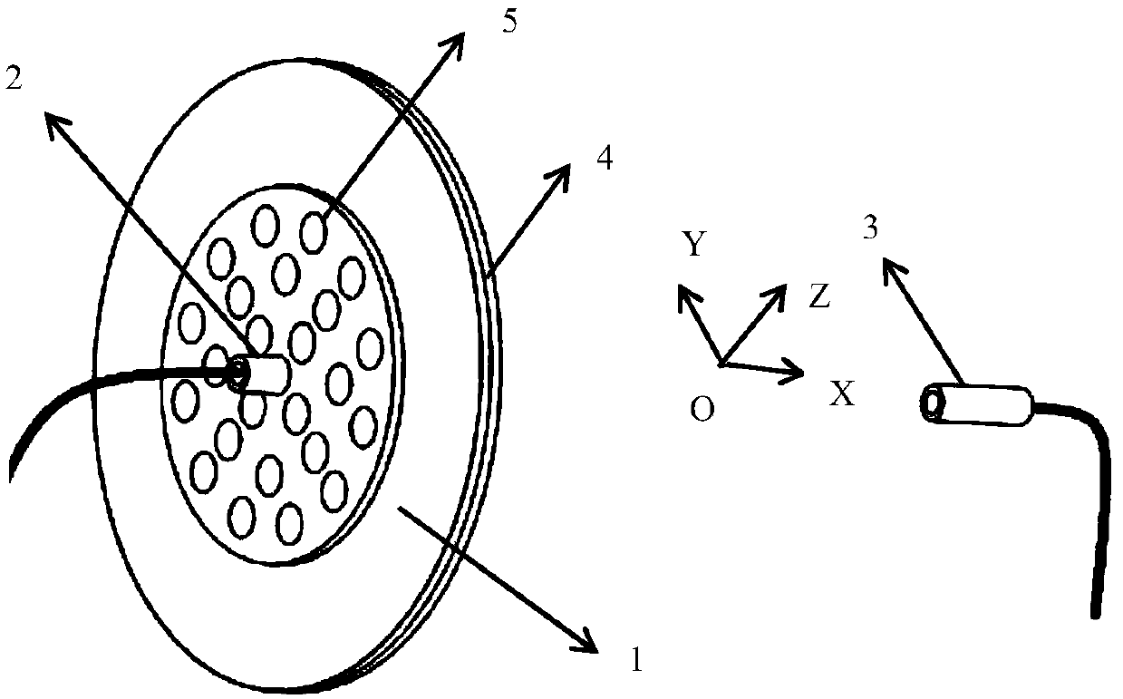
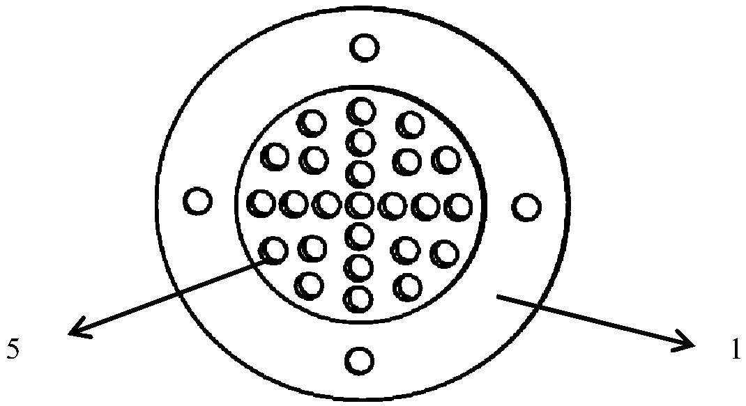
[0026] A method for manufacturing an optical fiber collimator array. The optical fiber collimator array includes a base 1 and an optical fiber collimator 2. The base 1 is provided with a number of mounting holes 5 corresponding to the number of optical fiber collimators.

[0027] The invention is described below by taking the 25-core fiber collimator shown in the accompanying drawings as a preferred embodiment.

[0028] Step 1, stick the heating device 4 on the surface of the base 1, and heat the base 1 to any temperature between 60°C and 150°C, preferably 60°C, 80°C, 120°C and 150°C in this embodiment , and keep heated throughout the production process.

[0029] Step 2, see figure 1 , observe through a microscope, adjust the coordinates of the fiber collimator 2 in the center mounting hole of the base through a fine-tuning device, install t...


PUM


Abstract

The invention relates to the field of optical communication, provides a manufacturing method of an optical fiber collimator array, and solves the technical problems that the optical axis direction of the emergent light of the optical fiber collimator array can be accurately ensured to be consistent in a low cost way and the position is accurate. The optical fiber collimator array comprises a pedestal equipped with array installing holes and optical fiber collimators. The optical fiber collimators are installed on the pedestal through one-to-one corresponding adjustment with reference collimators, and the angle of all the optical fiber collimators is adjusted to be consistent with that of the reference collimators so that the emergent light beams of the optical fiber collimator array can be mutually parallel. The optical fiber collimators are fixed in the installing holes of the pedestal through the binder and heating is performed through a heating ring in the curing process of the binder so that the objectives of accelerating curing and releasing stress in the heating process can be achieved. The manufacturing method of the optical fiber collimator array is simple in structure, low in cost and high in operability and can be widely applied to the array collimator structure of the multichannel optical communication system.

Description

technical field [0001] The invention belongs to the field of optical communication, and in particular relates to a manufacturing method of an optical fiber collimator array. Background technique [0002] With the rapid growth of modern communication data, communication requires more optical paths to transmit data at the same time than before, so higher requirements are placed on the bandwidth and capacity of communication. In order to meet this requirement, multi-core fiber collimator arrays are used in many optical devices. However, the fiber collimator array has relatively high requirements on the accuracy of the components and the processing and assembly technology, and it is necessary to ensure the parallelism between the outgoing beams in the fiber collimator array, as well as the accuracy of the position and the direction of the optical axis. At present, two production methods are generally used in the market to ensure the above characteristics of the fiber collimator...

Claims


Application Information

Patent Timeline
Patent Type & Authority Patents(China)
IPC IPC(8): G02B27/30
CPCG02B27/30
Inventor 梁礼晔王芳刘宇林黄骏周雅娴
Owner THE 23RD RES INST OF CHINA ELECTRONICS TECH GRP CORP
Features
  • R&D
  • Intellectual Property
  • Life Sciences
  • Materials
  • Tech Scout
  • Unparalleled Data Quality
  • Higher Quality Content
  • 60% Fewer Hallucinations
Learn More