Refrigeration cycle device

A refrigeration cycle and refrigerant technology, applied in the direction of refrigerators, refrigeration components, refrigeration and liquefaction, etc., can solve the problems of longer construction time, higher construction costs, higher material costs, etc., to achieve compactness and shorten construction time , The effect of reducing construction costs

Active Publication Date: 2019-08-06
MITSUBISHI ELECTRIC CORP
View PDF7 Cites 0 Cited by
  • Summary
  • Abstract
  • Description
  • Claims
  • Application Information

AI Technical Summary

Problems solved by technology

Therefore, since the construction of the jumper piping becomes complicated on site, and the material cost of the piping becomes high, there is a problem that the construction time becomes longer and the construction cost increases.

Method used


Image

  • Refrigeration cycle device
  • Refrigeration cycle device
  • Refrigeration cycle device

Examples


Embodiment approach 1

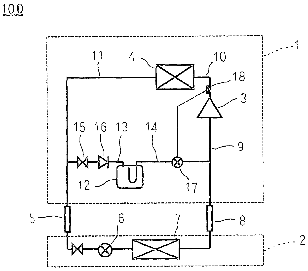
[0025] figure 1 It is a refrigerant circuit configuration diagram of the refrigeration cycle apparatus according to Embodiment 1 of the present invention.

[0026] exist figure 1 Among them, the refrigeration cycle device 100 is provided with: a heat source unit 1, the heat source unit 1 is installed outdoors; a cooling unit 2, the cooling unit 2 is installed in a cooling object, such as a store such as a convenience store or a supermarket; and a refrigerant storage tank 12, The refrigerant storage tank 12 stores refrigerant. Furthermore, the heat source unit 1 and the cooling unit 2 are connected via a liquid side bridging pipe 5 and a gas side bridging pipe 8 .

[0027] The heat source unit 1 includes a compressor 3 for compressing refrigerant and a condenser 4 as a heat source side heat exchanger. The suction side of the compressor 3 is connected to a gas side jumper pipe 8 via a gas side refrigerant pipe 9 . In addition, the discharge side of the compressor 3 is connec...

Embodiment approach 2

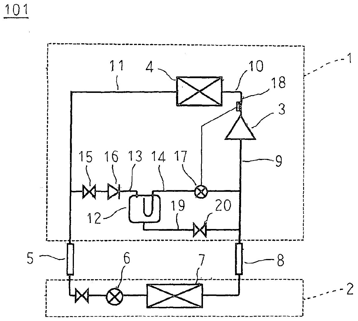
[0056] figure 2 It is a refrigerant circuit configuration diagram of a refrigeration cycle apparatus according to Embodiment 2 of the present invention.

[0057] exist figure 2 Among them, the refrigerant return pipe 19 is arranged to connect the lower part of the refrigerant storage tank 12 and the gas side refrigerant pipe 9 . An outlet-side solenoid valve 20 that is energized and opened is provided on the refrigerant return pipe 19 .

[0058] In addition, other configurations are configured in the same manner as in the first embodiment.

[0059] The refrigeration cycle device 101 according to Embodiment 2 operates in the same manner as the above-mentioned refrigeration cycle device 100 while the outlet side solenoid valve 20 is opened during normal operation. In addition, when the refrigeration cycle device 101 stops abnormally, the outlet side electromagnetic valve 20 is closed and operates in the same manner as the refrigeration cycle device 100 described above.

[...

Embodiment approach 3

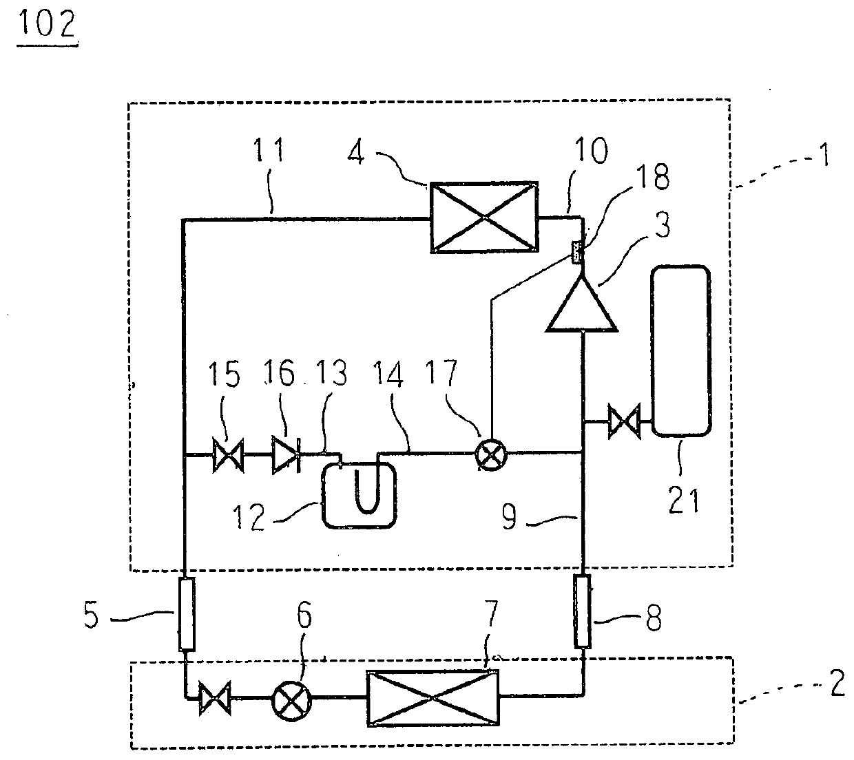
[0064] image 3 It is a refrigerant circuit configuration diagram of a refrigeration cycle apparatus according to Embodiment 3 of the present invention.

[0065] exist image 3 Among them, the expansion tank 21 is connected to the gas-side refrigerant piping 9 that is the suction side of the compressor 3 .

[0066] In addition, other configurations are configured in the same manner as in the first embodiment.

[0067] In the refrigeration cycle apparatus 102 according to Embodiment 3, the expansion tank 21 is connected to the gas-side refrigerant pipe 9 , so that the internal volume of the main refrigerant circuit can be enlarged, and pressure rise in the main refrigerant circuit can be prevented. If the expansion tank 21 is installed separately, a large tank volume is required, and there is a possibility that the installation space and the cost are not practical. In Embodiment 3, since the expansion tank 21 and the refrigerant storage tank 12 are used together, the refrige...


PUM


Abstract

The object of the present invention is to obtain a refrigeration cycle device that can recover the refrigerant in the liquid side jumper pipe at the time of stop even if the liquid side jumper pipe for low-pressure refrigerant is used, thereby suppressing the generation of the liquid side jumper pipe. The problem of pressure resistance can be solved, the construction time can be shortened, the construction cost can be reduced, and the compactness of the refrigerant storage tank can be realized. The refrigeration cycle device of the present invention includes: a liquid-side connection pipe extending from the liquid-side refrigerant pipe; a gas-side connection pipe extending from the gas-side refrigerant pipe; and a refrigerant storage tank whose suction side is connected to the liquid-side connection pipe. The discharge side is connected to the gas side connecting pipe to store the refrigerant; the inlet side solenoid valve is arranged on the liquid side connecting pipe and is opened when there is no power; the inlet side check valve is arranged on the liquid side connecting pipe to keep the refrigerant The flow is only to the refrigerant storage tank side; and the valve device is arranged on the gas side connecting pipe, is opened when the inlet side solenoid valve is energized, and is blocked with a delay after the inlet side solenoid valve is deenergized.

Description

technical field [0001] The present invention relates to a refrigeration cycle device for applications such as freezing and refrigeration. Background technique [0002] A conventional refrigeration cycle device includes an outdoor unit having a compressor and a heat source-side heat exchanger, an indoor unit having a use-side heat exchanger and a throttling device, and refrigerant piping connecting them, a compressor, a heat source-side heat exchanger, and a throttling device. The device and the use-side heat exchanger are connected by piping (for example, refer to Patent Document 1). [0003] In recent years, from the viewpoint of environmental protection, HFC-based refrigerants (fluorocarbons that do not contain chlorine) and R404A refrigerants (R-125, R-134a, R-143a) with zero ozone destruction coefficients have been used for mixed refrigeration. Refrigerant), R410A refrigerant (R32 is 50wt%, R125 is 50wt%) etc. as the refrigerant sealed in the refrigeration cycle device....

Claims


Application Information

Patent Timeline
Patent Type & Authority Patents(China)
IPC IPC(8): F25B1/00F25B45/00
CPCF25B45/00F25B7/00F25B31/006F25B40/00F25B2309/061F25B2400/13F25B2500/01F25B2500/27F25B2600/23F25B2600/2523F25B2700/21152F25B9/008F25B49/02F25B2339/044F25B2500/07
Inventor 石川智隆
Owner MITSUBISHI ELECTRIC CORP
Why Eureka
Try Eureka