Electrophotographic member, image heating device, image forming device and method for manufacturing electrophotographic member

A technology of electrophotography and heating device, which is applied to the equipment of electric recording process using charge pattern, electric recording process using charge pattern, chemical instrument and method, etc., which can solve the problem that it is difficult to obtain the adhesion between the elastic layer and the release layer and other problems, to achieve the effect of excellent thermal conductivity and excellent thermal conductivity

Active Publication Date: 2017-08-18
CANON KK
View PDF11 Cites 1 Cited by
  • Summary
  • Abstract
  • Description
  • Claims
  • Application Information

AI Technical Summary

Problems solved by technology

[0003] However, fluororesins, which originally have high mold release properties, are less likely to adhere to the surface of the

Method used


Image

  • Electrophotographic member, image heating device, image forming device and method for manufacturing electrophotographic member
  • Electrophotographic member, image heating device, image forming device and method for manufacturing electrophotographic member
  • Electrophotographic member, image heating device, image forming device and method for manufacturing electrophotographic member

Examples


Embodiment 1-1

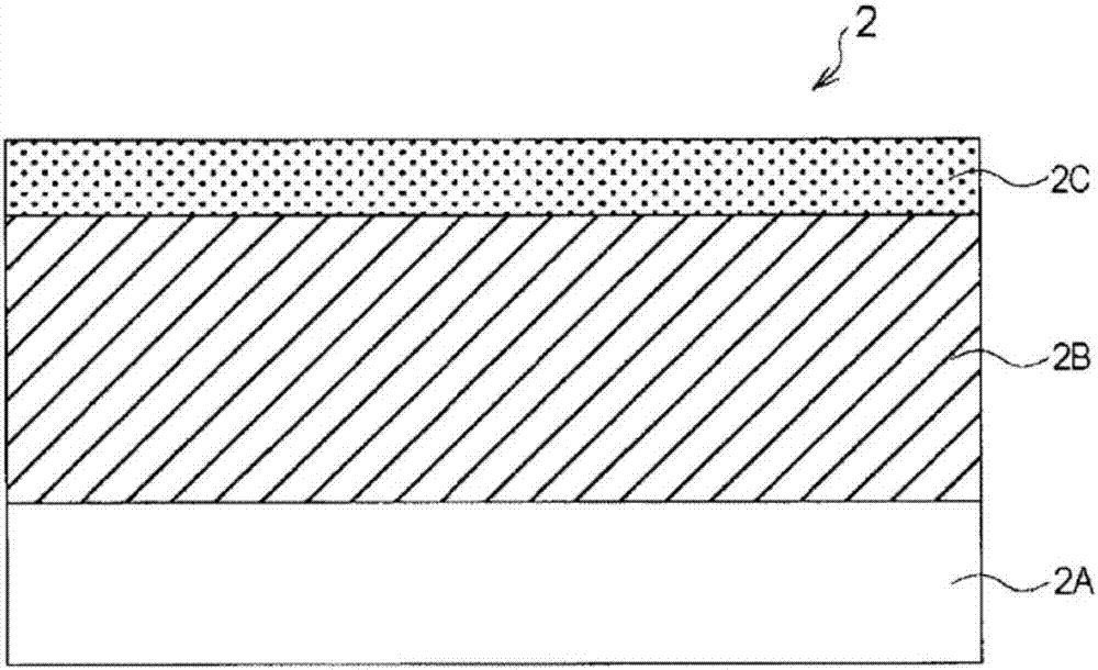
[0140] (10-1) Step of forming elastic layer 2B of fixing film

[0141] A metal belt (soft endless belt member) made of SUS with a length of 240 mm, a thickness of 40 μm, and an outer diameter of 30 mm was used as the base material 2A. For an area of ​​230 mm in length other than both ends of 5 mm on the outer peripheral surface, a rubber-based primer (trade name: X-33-174A / B from Shin-Etsu Silicone Co., Ltd.) was used, and applied to On the substrate 2A, a primer layer was applied in a thin and uniform manner. Then, it was put into an electric oven and dried at 200° C. for 30 minutes. In addition, for the material of the elastic layer 2B, a well-known addition-curable liquid silicone rubber (trade name: "KE-1281-A / B", available from Shin-Etsu Silicone Co., Ltd.) having a methyl group in a side chain was used. ), into which was mixed a crushed metal silicon filler (trade name: M-Si #600 from KINSEI MATEC CO., LTD.) with an average particle diameter of about 6.0 μm as a therma...

Embodiment 1-2、1-3

[0158] Fixing films 2 according to Examples 1-2 and 1-3 were each prepared in the same manner as in Example 1-1, except that the integrated amount of light from ultraviolet rays was adjusted to the value listed in Table 1, and carried out evaluate. The evaluation results are shown in Table 1. In this embodiment, with regard to adhesiveness, the mode of failure was also cohesive failure within the elastic layer 2B.

Embodiment 2-1

[0160] Except that a low-pressure mercury UV lamp (trade name: GLQ500US / 11, from TOSHIBA LIGHTING & TECHNOLOGY CORPORATION (formerly HARISONTOSHIBA LIGHTING Corporation)) having a center wavelength of 254 nm was used instead of an excimer UV lamp in the step of bonding the elastic layer 2B and the release layer 2C. (Trade name: MEUT-1-500 from M.D. Excimer Inc.) Except as a light source, a fixing film 2 was prepared in the same manner as in Example 1, and evaluated. The evaluation results are shown in Table 1. In this example, in the adhesiveness evaluation, the failure mode was also cohesive failure in the elastic layer 2B.


PUM

PropertyMeasurementUnit
Thicknessaaaaaaaaaa
Tensile strengthaaaaaaaaaa
Thicknessaaaaaaaaaa

Abstract

Provided is an electrophtographic member wherein an elastic layer containing a silicone rubber is sufficiently adhered to a mold-release layer containing a fluororesin without via any adhesive layer. The electrophtographic member comprises a base material, an elastic layer containing a silicone rubber that is disposed on the base material, and a mold-release layer that is provided on the surface of the elastic layer directly in contact therewith, wherein: the mold-release layer contains a fluororesin selected from the group consisting of PFA, FEP, PTFE, ETFE, PCTFE, ECTFE and PVDF; and the elastic layer undergoes cohesive failure in a 90degree peel bond strength test in accordance with Japanese Industrial Standards (JIS) K 6854-1:1999.

Description

technical field [0001] The present invention relates to a member for electrophotography preferably used as a fixing member of an electrophotographic image forming apparatus such as a copying machine and a printer (hereinafter also referred to as an “image forming apparatus”), an image heating apparatus, an image forming apparatus, and the electrophotography The method of manufacturing the component. Background technique [0002] Fixing members of image heating devices used in image forming devices such as copiers, printers, and facsimiles are generally members each including at least an elastic layer and a release layer containing a fluororesin on a heat-resistant base material. An elastic layer composed of silicone rubber having a surface covered with an extrusion-molded fluororesin tube is mainly used as a fixing member. [0003] However, a fluororesin inherently having high release properties is less likely to adhere to the surface of the elastic layer of silicone rubber...

Claims


Application Information

Patent Timeline
IPC IPC(8): G03G15/20B32B25/16G03G15/00
CPCB32B25/16B32B7/06B32B7/12B32B15/06B32B25/02B32B25/042B32B25/08B32B25/20B32B27/20B32B27/285B32B27/304B32B27/308B32B27/322G03G15/2057B32B2250/03B32B2250/24B32B2262/106B32B2264/102B32B2264/105B32B2264/107B32B2307/54B32B2307/546B32B2307/5825B32B2307/732B32B2307/748B32B2457/00B32B2559/00B32B2597/00
Inventor 松本真持大岛義人
Owner CANON KK
Why Eureka
Try Eureka