Vibration cutting process diagnostic device

A vibration cutting and diagnosis device technology, which is applied in the direction of automatic control devices, metal processing equipment, metal processing machinery parts, etc., can solve problems such as vibration, mechanical inherent vibration, and reduced processing accuracy

Active Publication Date: 2017-08-18
MITSUBISHI ELECTRIC CORP
View PDF9 Cites 5 Cited by
  • Summary
  • Abstract
  • Description
  • Claims
  • Application Information

AI Technical Summary

Problems solved by technology

On the other hand, high-speed and high-precision position control is required in motor control devices for machine tools. If the feed rate is increased for high speed, or the control g

Method used


Image

  • Vibration cutting process diagnostic device
  • Vibration cutting process diagnostic device
  • Vibration cutting process diagnostic device

Examples


Embodiment approach 1

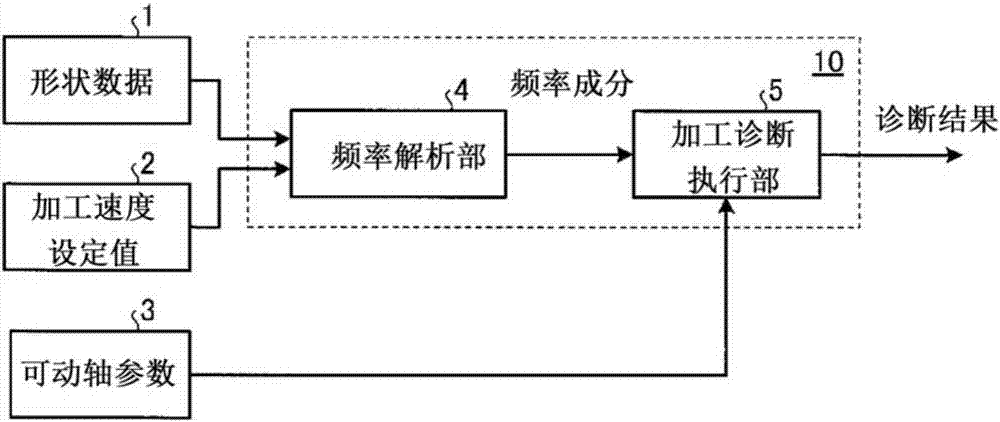
[0023] figure 1 It is a block diagram showing the configuration of the vibration cutting machining diagnosis device according to Embodiment 1 of the present invention. figure 1 The vibration cutting machining diagnosis device 10 shown is for diagnosing whether the vibrating cutting machining in which the cross-sectional shape of the object to be machined is processed into a non-circular shape by the reciprocating motion of the linear feed axis of the tool post 14 as the movable axis is performed. The vibration cutting machining diagnosis device 10 has a frequency analysis unit 4 that reads the shape data 1 and the machining speed setting value 2 of the object to be machined, and based on them, analyzes the frequency included in the position command signal of the movable shaft. components; and a processing diagnosis execution unit 5, which diagnoses whether the machining speed setting value 2 can be performed according to the shape data 1 based on the frequency components calcu...

Embodiment approach 2

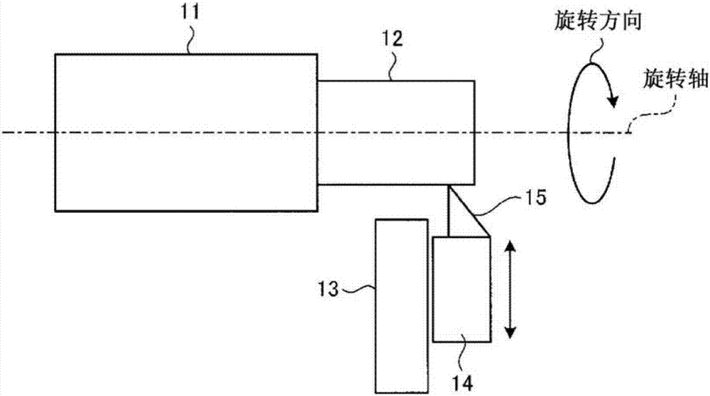
[0032] The difference between the configuration of the second embodiment and the configuration of the first embodiment is that the control system of the movable axis, that is, the linear feed axis of the tool post, is a control system composed of feedback control and a notch filter. The position response characteristic of the control system of the tool post drive unit 13 is the characteristic of a band-stop filter in which the gain of the frequency band specified by the parameter of the notch filter is attenuated. The cut-off frequency band of the band-stop filter is included in the movable axis parameter 3. Here, the lower limit of the cut-off frequency band of the band-stop filter is set to F min [Hz], set the upper limit to F max [Hz]. In addition, it is assumed that the frequency component displaced in the radial direction of the cross-sectional shape of the workpiece 12 to be machined includes a harmonic component twice the rotational frequency of the turning spindle 11...

Embodiment approach 3

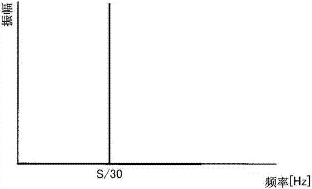
[0036] The structure of the third embodiment differs from the first embodiment in that there is mechanical anti-resonance in the shaft feed system of the linear feed shaft of the tool post which is a movable shaft. The position response characteristic of the linear feed axis is that the gain decreases at the anti-resonance frequency. In addition, the cross-sectional shape of the workpiece processed in the third embodiment is the same as that in the first embodiment, and the frequency components included in the position command signal are assumed to be as follows: image 3 shown.

[0037] The anti-resonance frequency of the mechanical system is included in the movable axis parameter 3, and the anti-resonance frequency is set to F a [Hz]. In Embodiment 3, if the anti-resonant frequency of the linear feed axis of the tool post 14, that is, F a [Hz] and the frequency S / 30[Hz] match, the machining diagnosis execution unit 5 diagnoses that machining is not possible, and if they d...


PUM


Abstract

The purpose of the present invention is to obtain a vibration cutting process diagnostic device such that, when performing a vibration cutting process for processing the cross sectional shape of an object to be processed into a non-perfect circular shape by reciprocating a tool, whether the process can be performed under a speed condition designating a vibration cutting can be diagnosed prior to the process. A vibration cutting process diagnostic device that makes a diagnosis as to whether a vibration cutting process for processing the cross sectional shape of an object to be processed into a non-perfect circular shape can be performed by a reciprocating motion of a movable axis is provided with: a frequency analysis unit (4) that computes, on the basis of shape data (1) which are processing shape data of a work as the object to be processed and a processing speed set value (2), a frequency component included in a movable axis position command signal; and a processing diagnosis implementation unit (5) that makes a diagnosis as to the possibility of processing the shape data (1) with the processing speed set value (2), on the basis of the frequency component and a movable axis parameter (3) of the movable axis.

Description

technical field [0001] The present invention relates to a vibrating cutting process diagnostic device capable of diagnosing whether or not the process can be performed before the process is performed during the vibratory cutting process in which the cross-sectional shape of the object to be processed is processed into a non-circular shape by reciprocating a tool. processing. Background technique [0002] With regard to machine tools that perform cutting processing, various processing devices and processing methods have been proposed in order to realize processing that cannot be realized by conventional techniques. Vibration cutting of non-circular shapes realized by reciprocating a turning tool at high speed is one example. [0003] In conventional turning, in a machine having a spindle for rotating a workpiece and a linear feed axis for moving a turning tool as an example of a tool in the radial direction of the workpiece, by moving the tool to the linear By feeding the c...

Claims


Application Information

Patent Timeline
IPC IPC(8): G05B19/406B23B1/00B23B5/24
CPCB23B5/36G05B19/406G05B2219/37087G05B2219/39241Y02P90/02B23Q15/013B23Q15/08G05B19/4065
Inventor 长冈弘太朗田边章东俊博
Owner MITSUBISHI ELECTRIC CORP
Why Eureka
Try Eureka