Periphery drive sludge scraping and sucking machine

A technology of peripheral transmission and dredger suction, which is applied to the feeding/discharging device, chemical instrument and method, and separation method of the settling tank, and can solve the problems of increasing the occupied area, high energy consumption in operation, and mud content in the mixture. Less problems, to achieve the effect of saving floor space, good mud discharge effect, and strong adaptability

Inactive Publication Date: 2017-08-22
山东贝特尔环保科技有限公司
View PDF0 Cites 0 Cited by
  • Summary
  • Abstract
  • Description
  • Claims
  • Application Information

AI Technical Summary

Problems solved by technology

However, since the water level difference between the liquid level of the sedimentation tank and the sludge collecting tank of the mud scraper is only 300 mm, the actual pressure difference is low, and the sludge fluidity is poor, resulting in longer sludge residence time in the sedimentation tank and worse sludge activity. The efficiency of biochemical treatment is reduced, and the lifting mixture contains less mud
At the same time, the slag scraping and mud scraping of the existing scraper and suction machine are set separately, resulting in a small processing capacity at one time, and the increased floor space of multiple devices. At the same time, the simultaneous operation of multiple devices consumes a lot of energy, and it needs If the sludge is sucked later, the concentration of the discharged activated sludge is low, and the sludge discharge effect is poor.

Method used


Image

  • Periphery drive sludge scraping and sucking machine
  • Periphery drive sludge scraping and sucking machine

Examples


Embodiment Construction

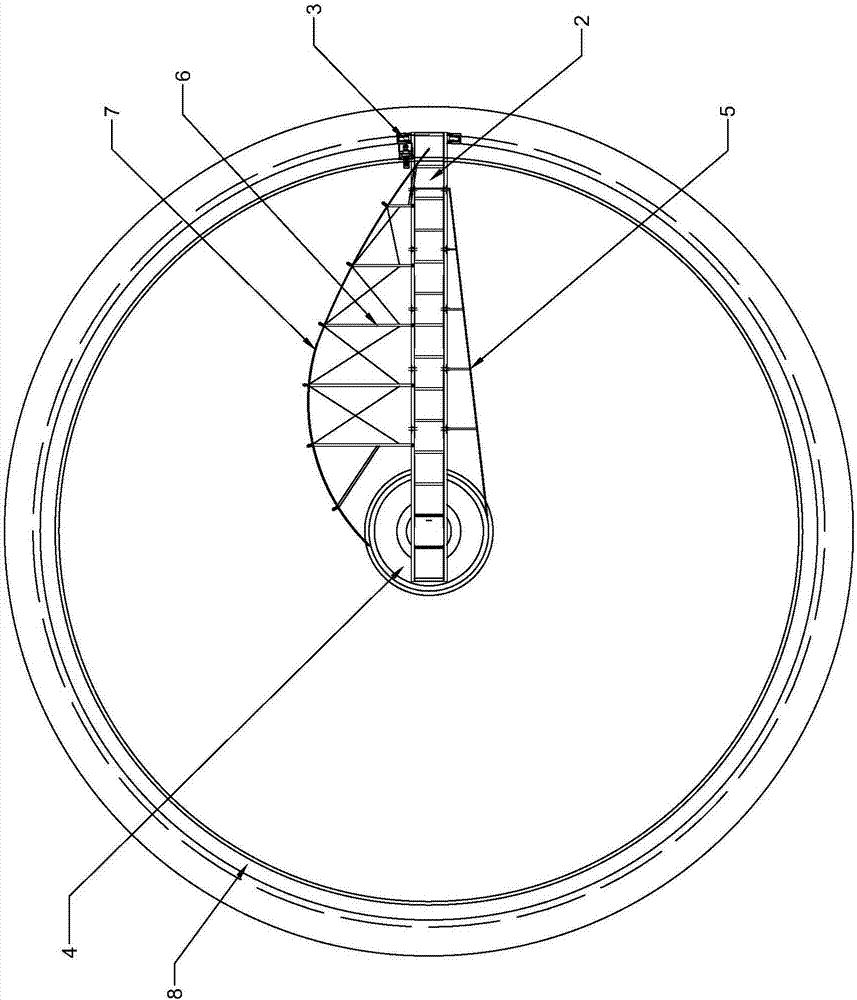
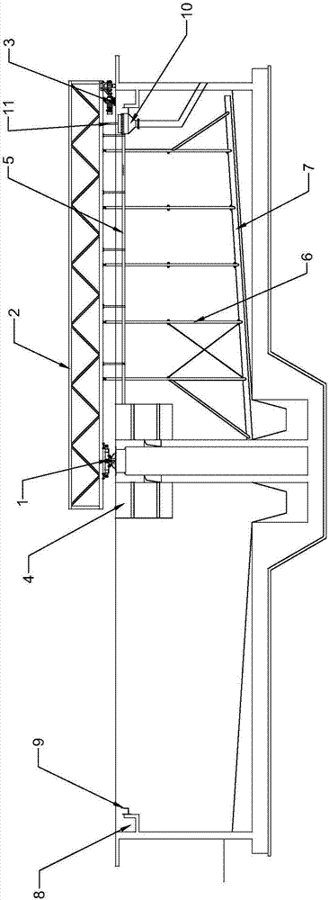
[0013] Such as figure 1 figure 2 As shown, the peripheral transmission scraper and suction machine consists of a slewing support device 1 arranged on the top of the central column of the circular pool body and a working bridge 2 fixed on the slewing support device 1 at one end. The other end of the working bridge 2 is provided with a The walking device 3 on the edge of the pool body, the top of the circular pool center column under the slewing support device 1 is provided with a plurality of steady flow cylinders 4, the periphery of the bottom of the circular pool body center column is a sludge sedimentation annular groove, and the working bridge 2 A horizontal slag scraper 5 is fixed at the bottom, and an arc-shaped scraper 7 is installed under the working bridge 2 through the scraper arm 6. The arc-shaped scraper 7 is close to the bottom of the pool body, and the outer edge of the pool is set on the inner wall. There is a ring-shaped overflow weir plate 8, and a ring of sc...


PUM


Abstract

The invention discloses a periphery drive sludge scraping and sucking machine. The two ends of a straight drum are provided with large end cover shafts respectively, one end of one large end cover shaft is provided with a conical drum, one end of the other large end cover shaft is sleeved with a labyrinth ring and connected with a large universal joint, the other end of the universal joint is connected with a planetary gear differential mechanism sleeved with a right bearing on a fixing base, the other end of the planetary gear differential mechanism is connected with a main belt pulley, one end of the conical drum is connected with a small end cover shaft, the small end cover shaft is sleeved with a left bearing, the surface of the small end cover shaft is provided with a liquid outlet, a solid material box is arranged below the small end cover shaft, the large end cover shaft at the other end is provided with a liquid outlet, a liquid material box is arranged below the large end cover shaft at the other end, a through cavity is formed in the small end cover shaft, the conical drum, the straight drum and the large end cover shafts, and a spiral barrel is arranged in the cavity. Thus, according to the periphery drive sludge scraping and sucking machine, adjustment can be carried out based on the water content, viscosity and the like of treated materials.

Description

technical field [0001] The invention relates to a peripheral transmission mud scraper and suction machine. Background technique [0002] The peripheral transmission scraper and suction dredger is mainly composed of a scum skimmer, a scum scraper and a slag discharge bucket. The generated transverse force pushes the scum to the side of the pool, and the scraping rake is used as an extension of the scum board, and is overlapped with the scum board by the sealing plate, and when the suction dredge moves to the slag discharge hopper, the scum is removed It is scraped into the bucket and discharged out of the pool by gravity. However, since the water level difference between the liquid level of the sedimentation tank and the sludge collecting tank of the mud scraper is only 300 mm, the actual pressure difference is low, and the sludge fluidity is poor, resulting in longer sludge residence time in the sedimentation tank and worse sludge activity. The efficiency of biochemical tr...

Claims


Application Information

Patent Timeline
Patent Type & Authority Applications(China)
IPC IPC(8): B01D21/24
CPCB01D21/245
Inventor 宋燕吴金宝
Owner 山东贝特尔环保科技有限公司
Why Eureka
Try Eureka