Cutting machine

A technology of cutting machine and cutting mechanism, which is applied in the direction of metal processing, etc., can solve the problems that the cutting depth cannot be effectively controlled, affects the cutting precision of the cutting machine, and the vibration of the cutting knife is large, so as to reduce the dust flying field, lower the temperature and improve the cutting precision Effect

Inactive Publication Date: 2017-08-22
柳州市昌泉贸易有限公司
View PDF9 Cites 2 Cited by
  • Summary
  • Abstract
  • Description
  • Claims
  • Application Information

AI Technical Summary

Problems solved by technology

When cutting various stone and plate materials, etc., it is usually necessary to control the cutting depth of the cutting machine, but the current cutting machine has a complex structure, and the cutting depth cannot be effectively controlled
At the same time, the cutter vibrates greatly during the working process of the cutting machine, which affects the cutting accuracy of the cutting machine.

Method used


Image

  • Cutting machine
  • Cutting machine

Examples


Embodiment 1

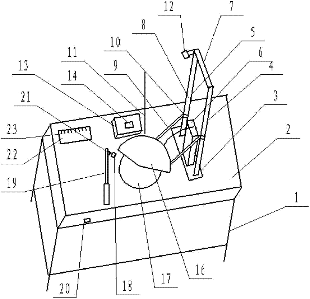
[0032] Such as Figure 1-Figure 2 , a cutting machine in this embodiment includes a frame 1, a workbench 2 is provided on the frame 1, a cutting mechanism and an automatic lifting mechanism are arranged on the workbench 2, and the cutting mechanism is located on the workbench 2, the automatic lifting mechanism is connected with the cutting mechanism through a connecting rod 9.

[0033] The automatic lifting mechanism includes a base 3, a first support rod 4 and a second support rod 5 arranged on the base 3, and is arranged between the first support rod 4 and the second support rod 5 and is located on the base 3 The upper lifting cylinder 6 and the limit rod 7 arranged on the ends of the first support rod 4 and the second support rod 5 . Both the first support rod 4 and the second support rod 5 are equipped with guide rails 8 , and the two connecting rods 9 connecting the automatic lifting mechanism and the cutting mechanism are provided with slide blocks 10 matched with the g...

Embodiment 2

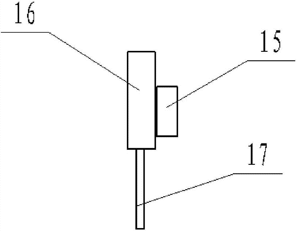
[0045] This embodiment is the same as embodiment 1 except that the raw material ratio and preparation method of the shock-absorbing material embedded in the cutter installation body 16 are different from those of embodiment 1.

[0046] The damping material of the present embodiment includes the following components by weight: 60 parts of bentonite, 40 parts of nitrile rubber, 20 parts of calcium carbonate, 15 parts of glass fiber, 15 parts of paraffin oil, 10 parts of alkyldiethanolamide, terpene 10 parts of resin, 8 parts of polyvinyl acetate, 8 parts of polyethylene terephthalate, 8 parts of tea saponin, 8 parts of xanthan gum and 5 parts of triethanolamine oleate.

[0047] Further, the preparation method of the shock absorbing material includes the following steps:

[0048] (1) Take the above-mentioned raw materials by weight;

[0049] (2) Put bentonite, polyethylene terephthalate and glass fiber bonded mixture, nitrile rubber, paraffin oil, polyvinyl acetate, terpene resi...


PUM


Abstract

The invention discloses a cutting machine, which belongs to the technical field of electric machinery. The cutting machine includes a frame, on which a workbench, a cutting mechanism and an automatic lifting mechanism are arranged, the cutting mechanism is arranged above the workbench, and the automatic lifting mechanism is connected with the cutting mechanism through a connecting rod. The lifting cylinder in the automatic lifting mechanism is connected with the cutting mechanism, the air source is turned on, and the lifting cylinder drives the cutting mechanism to move downward along the guide rails on the first support rod and the second support rod in the automatic lifting mechanism. A vertical scale is set on the workbench, a camera is set on the automatic lifting mechanism, and a control device is also set on the workbench. Both the camera and the pressure regulating valve of the lifting cylinder are electrically connected to the control device; Touch screen for cutting depth. The cutting machine of the invention can not only effectively control the cutting depth, but also greatly reduce the vibration of the cutting knife during the working process of the cutting machine, and improve the cutting precision.

Description

technical field [0001] The invention relates to the technical field of electric machinery, in particular to a cutting machine. Background technique [0002] In the process of mechanical processing, the common methods of plate cutting include manual cutting, semi-automatic cutting machine cutting and CNC cutting machine cutting. Manual cutting is flexible and convenient, but manual cutting has poor quality, large dimensional errors, large material waste, and heavy follow-up processing workload. At the same time, the working conditions are harsh and the production efficiency is low. Among the particular semi-automatic cutting machines, the profiling cutting machine has good quality of cutting workpieces. As it uses a cutting expire, it is not suited to single-piece, small-batch and large-scale reducing. Although other types associated with semi-automatic cutting machines minimize the labor intensity regarding workers, their functions are simple and therefore are only suitable...

Claims


Application Information

Patent Timeline
Patent Type & Authority Applications(China)
IPC IPC(8): B26D1/18B26D7/00B26D5/04C08L9/02C08L91/06C08L45/00C08L31/04C08L67/02C08L5/00C08K13/04C08K3/34C08K7/14C08K5/20C08J9/08
CPCB26D1/18B26D5/04B26D7/00C08J9/08C08J2203/02C08J2309/02C08L9/02C08L2201/08C08L2203/14C08L2205/035
Inventor 蓝豆
Owner 柳州市昌泉贸易有限公司
Why Eureka
Try Eureka