Novel plane magnetron sputtering cathode with high target material utilization rate

A magnetron sputtering and cathode technology, applied in the field of magnetron sputtering, can solve the problems of high cost, formation of pollution, insufficient application surface of high-speed rotating magnet, etc., and achieve the effect of improving utilization rate and maintaining stability

Active Publication Date: 2017-08-22
三河市衡岳真空设备有限公司
View PDF3 Cites 16 Cited by
  • Summary
  • Abstract
  • Description
  • Claims
  • Application Information

AI Technical Summary

Problems solved by technology

With the occurrence of sputtering, once the sputtering runway on the target is punctured, the target can no longer be used, and a new target needs to be replaced, resulting in a very low utilization rate of the target, usually only 30%~40%
The sputtering target is the main consumable of magnetron sputtering, and the low utilization rate will undoubtedly cause a great waste of the target, resulting in an increase in the cost of sputtering
[0006] Second, without changing the sputtering process conditions, as the sputtering runway 12 on the target 1 gradually deepens, the sputtering rate will gradually decrease
In practical applications, the coating process requires sputtering to maintain a stable rate. In view of this situation, if the existing planar magnetron sputtering cathode is used, it will have a certain impact on the quality of the coating process.
[0007] Third, some impurities will accumulate in regions other than the sputtering runway 12 on the target material 1 that are not bombarded by ions. During the coating process, the impurities on the surface of these regions will also partially Released and incorporated into the film, it will reduce the purity of the coating and form pollution
This method starts from the structure of the target instead of the structure of the planar magnetron sputtering cathode. Although the utilization rate of the target can be improved to a certain extent, there are still some problems.
First of all, since the thickness of the target is limited by the strength of the magnetic field, it cannot be thickened without limit, so the improvement of the utilization rate of the target is correspondingly limited, and the degree of improvement is about 5%-10%.
Secondly, changing the target material from flat to ir

Method used


Image

  • Novel plane magnetron sputtering cathode with high target material utilization rate
  • Novel plane magnetron sputtering cathode with high target material utilization rate
  • Novel plane magnetron sputtering cathode with high target material utilization rate

Examples


Embodiment Construction

[0063] In order to better understand and illustrate the present invention, the present invention will be further described in detail below in conjunction with the accompanying drawings.

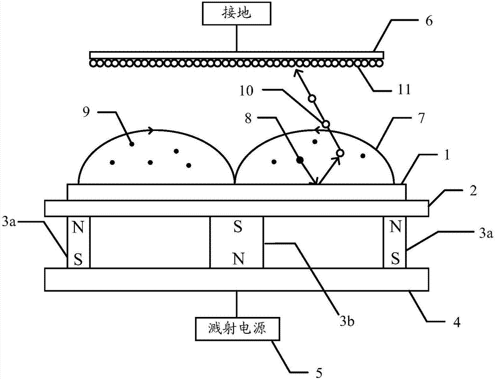
[0064] The invention provides a planar magnetron sputtering cathode. Please refer to Figure 9 , Figure 9 It is a structural cross-sectional schematic view of a specific embodiment of the planar magnetron sputtering cathode according to the present invention. Such as Figure 9 As shown, the planar magnetron sputtering cathode includes a target 100, a back plate 400, a magnet device and a magnetically conductive plate 300, the target 100 is arranged on one side of the back plate 400, and the magnetically conductive plate 300 is set On the other side of the back plate 400, the magnet device is arranged between the back plate 400 and the magnetic conductive plate 300, wherein:

[0065] The magnet arrangement comprises a central magnet 220 and an outer magnet 210 surrounding the central magn...


PUM


Abstract

The invention provides a novel plane magnetron sputtering cathode. The plane magnetron sputtering cathode comprises a target material, a backboard, a magnet device and a magnetic conductive plate. The target material is arranged at one side of the backboard, and the magnetic conductive plate is arranged at the other side of the backboard. The magnet device is arranged between the backboard and the magnetic conductive plate. The magnet device comprises a middle magnet and an outer ring magnet surrounding the middle magnet. The middle magnet comprises at least two electromagnets. The polarities of magnetic poles, facing the target material, of the outer ring magnet and the middle magnet are opposite. The plane magnetron sputtering cathode further comprises an electromagnet power source. The electromagnet power source is connected with the at least two electromagnets and supplies power to the at least two electromagnets in sequence so that magnetic field distribution between the outer ring magnet and the middle magnet can be changed continuously. By implementing the novel plane magnetron sputtering cathode, the target material utilization rate can be effectively increased, pollution to the target material is prevented, and stability of the sputtering speed is improved. In addition, the plane magnetron sputtering cathode provided by the invention has the characteristics of being simple in structure, easy to control and high in reliability.

Description

technical field [0001] The invention relates to the technical field of magnetron sputtering, in particular to a planar magnetron sputtering cathode. Background technique [0002] At present, in the application field of magnetron sputtering coating technology, the most widely used is the planar magnetron sputtering cathode. Please refer to figure 1 , figure 1 It is a schematic diagram of the working principle of the planar magnetron sputtering cathode in the prior art. Such as figure 1 As shown, an existing typical planar magnetron sputtering cathode includes a target 1 , a copper back plate 2 , a magnet device and a magnetically conductive plate 4 . Specifically, the target 1 is disposed on the copper back plate 2, wherein the side of the target 1 facing the external space is used for sputtering. The magnet device and the magnetic conductive plate 4 are arranged on the other side of the copper back plate 2 , wherein the magnet device is arranged between the back plate 2...

Claims


Application Information

Patent Timeline
IPC IPC(8): C23C14/35
Inventor 张诚
Owner 三河市衡岳真空设备有限公司
Why Eureka
Try Eureka