Micro nano motor based on shearing piezoelectric stacks

A piezoelectric stack and micro technology, applied in piezoelectric effect/electrostrictive or magnetostrictive motors, electrical components, generators/motors, etc., can solve the problem of single installation direction, weak anti-interference ability, and external Vibration sensitivity and other problems, to achieve the effect of good rigidity and stepping accuracy, less voltage drive signal, and strong structural rigidity

Pending Publication Date: 2017-08-22
NANJING UNIV OF POSTS & TELECOMM
View PDF5 Cites 3 Cited by
  • Summary
  • Abstract
  • Description
  • Claims
  • Application Information

AI Technical Summary

Problems solved by technology

The force between the slider and the guide rail of the motor is maintained by gravity, which is sensitive to external vibrations, so the anti-interference ability is weak, and the installation direction is single, and the guide rail cannot be placed vertically or obliquely.
[0008] (3) Koala type piezoelectric motor: use two piezoelectric scanning tubes in series, use three sets of springs fixed on the top, middle and bottom of the piezoelectric scanning tube to squeeze and fix the sliding rod placed in the center, and then control it by pulse voltage signal The orderly expansion and contraction of the two piezoelectric scanning tubes realizes the approach of the probe to the sample. After the stepping is completed, the third piezoelectric scanning tube is used for scanning, and the processing and assembly accuracy of the three sets of springs are very high. The structure low stability

Method used


Image

  • Micro nano motor based on shearing piezoelectric stacks
  • Micro nano motor based on shearing piezoelectric stacks
  • Micro nano motor based on shearing piezoelectric stacks

Examples


Embodiment Construction

[0024] The present invention is described in further detail now in conjunction with accompanying drawing.

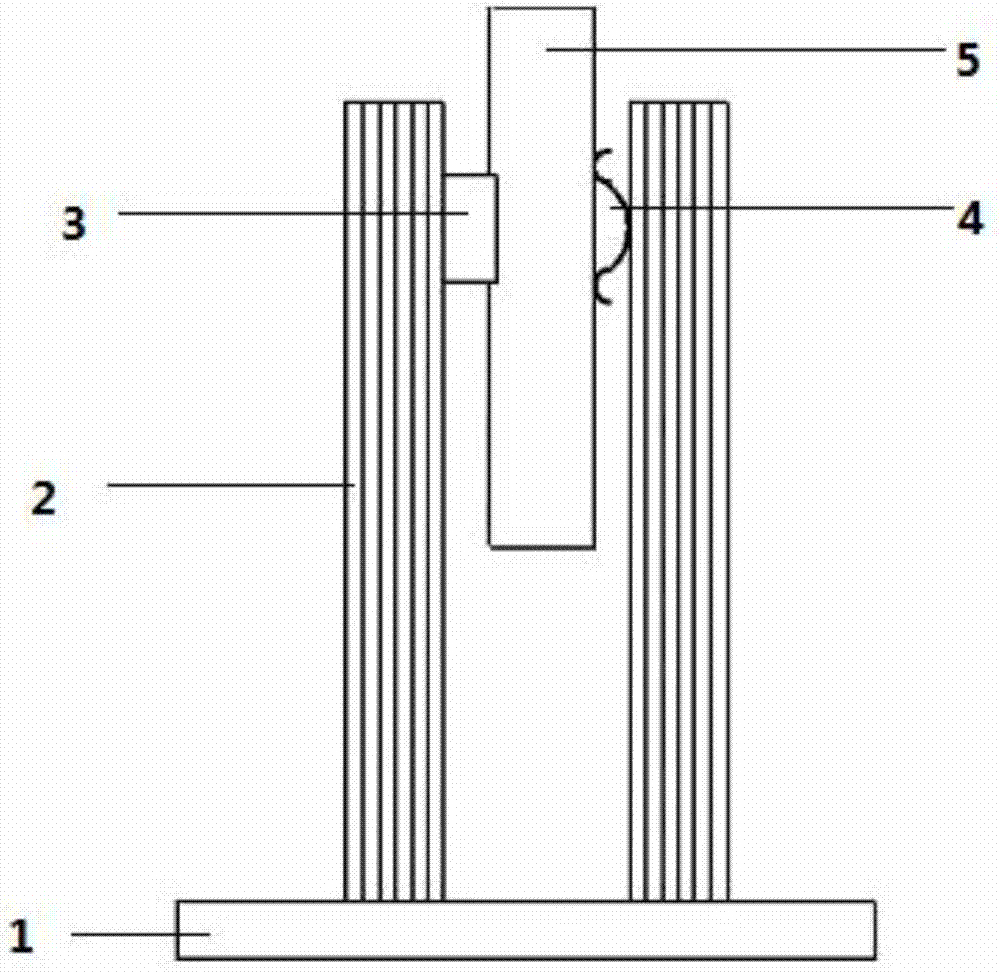
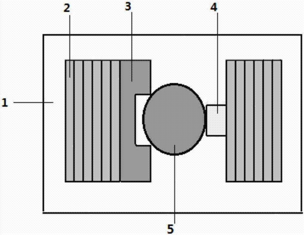
[0025] Based on various drawbacks of the motors in the prior art, the present invention makes corresponding improvements to the existing motor structure. First, the cylindrical insulating guide rail is replaced with a rectangular parallelepiped guide groove, because the design of this guide groove fits better with the shear piezoelectric stack, which can improve the structural rigidity and greatly reduce the difficulty of assembly. Secondly, a groove with a width slightly smaller than the diameter of the slide bar is vertically provided in the middle of the free end of the cuboid guide groove, and the two edges of the groove support the slide bar to replace the four silicon nitride balls in the previous structure, so that It not only improves the precision of the structure, but also reduces the frictional force between the force transmission block and the slide bar.

[...


PUM


Abstract

The invention discloses a micro nano motor based on shearing piezoelectric stacks. The motor comprises a substrate, two shearing piezoelectric stacks, a rigid guidance groove, an adjustable flexible force transmission block and a slide rod. The positive electrode of one of the shearing piezoelectric stacks is short circuited with the negative electrode of another shearing piezoelectric stack, and a voltage driving signal is imposed on the shearing piezoelectric stacks. The shearing piezoelectric stacks are parallely fixed on the substrate according to a telescoping direction. The rigid guidance groove and the adjustable flexible force transmission block are respectively adhered to opposite faces of free ends of the shearing piezoelectric stacks. Two edges of the rigid guidance groove and the adjustable flexible force transmission block are used for fixing the slid rod between the shearing piezoelectric stacks in a squeezing manner. The squeezing force pressure meets the condition that the maximum static frictional force between the force transmission block and the slide rod is slightly larger than the gravity of the slide rod. According to the invention, the rigid guidance groove and the adjustable flexible force transmission block are used for fixing the slid rod, so the motor is simple in structure, easy to process, highly rigid and suitable for use in a scanning probe microscope and a fine tuning positioning device of a precision optical system under an extreme condition.

Description

technical field [0001] The invention belongs to the technical field of piezoelectric positioners, and relates to a micro-drive system, in particular to a micro-nano motor based on a shear piezoelectric stack. Background technique [0002] Nanotechnology is a science and technology that uses single atoms and molecules to manufacture substances, and studies the properties and applications of materials with structural dimensions in the range of 0.1 to 100 nanometers. With the development of nanoscience and technology, a series of new science and technology have been triggered, such as nanophysics, nanobiology, nanochemistry, nanoelectronics, nanoprocessing technology and nanometrics, and nanomotors are nanotechnology Novel microactuation systems for nanopositioning and nanomeasurement under study. [0003] Nanomotor is a piezoelectric positioner that can realize nanometer-level positioning accuracy and centimeter-level travel at the same time. It mainly relies on the cumulativ...

Claims


Application Information

Patent Timeline
Patent Type & Authority Applications(China)
IPC IPC(8): H02N2/02H02N2/04
CPCH02N2/025H02N2/043
Inventor 庞宗强张悦
Owner NANJING UNIV OF POSTS & TELECOMM
Why Eureka
Try Eureka