Hydraulic feeding mechanical hand

A manipulator and hydraulic technology, applied in the direction of manipulators, program-controlled manipulators, auxiliary devices, etc., can solve problems such as potential safety hazards, inability to control strokes, and inability to operate devices, so as to eliminate potential safety hazards, have good guiding performance, and ensure safety. Effect

Pending Publication Date: 2017-08-25
TAIZHOU POLYTECHNIC COLLEGE
View PDF8 Cites 9 Cited by
  • Summary
  • Abstract
  • Description
  • Claims
  • Application Information

AI Technical Summary

Problems solved by technology

The structure design of the existing loading manipulator is unreasonable. When the loading manipulator moves up and down again, the guide sleeve is likely to slide and tilt, posing a safety hazard. The tilt of the guide sleeve can easily cause the lifting position to be inaccurate; A downward impact force will be generated during the downward movement, which will easily cause damage to the internal parts of the device for a long time, resulting in the failure of the device to operate, and the safety of the device cannot be effectively guaranteed, and the components in the device cannot be controlled by each component during operation. The stroke is effectively controlled, the loss is high, and the life is short

Method used


Image

  • Hydraulic feeding mechanical hand
  • Hydraulic feeding mechanical hand
  • Hydraulic feeding mechanical hand

Examples


Embodiment Construction

[0032] The present invention will be further explained below in conjunction with the accompanying drawings and embodiments.

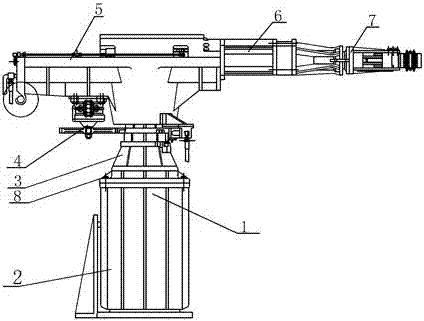
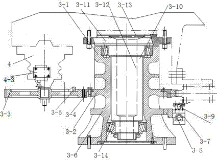
[0033] like Figure 1-7 As shown, a hydraulic feeding manipulator includes an arm assembly 1, a rotating wrist assembly 6 and a clamping hand assembly 7, and the arm assembly 1 and the clamping hand assembly 7 are connected through the rotating wrist assembly 6, The arm assembly 1 includes an arm lifting mechanism 2, an arm bearing positioning mechanism 3, an arm turning mechanism 4 and an arm telescoping mechanism 5. The arm lifting mechanism 2 is equipped with an arm bearing positioning mechanism 3 and is fixedly connected by fastening bolts 8. The arm bearing and positioning mechanism 3 is equipped with an arm turning mechanism 4 and adapted thereto, and the arm turning mechanism 4 is provided with an arm telescoping mechanism 5 adapted thereon.

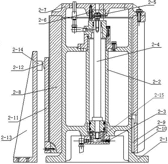
[0034] The bottom of the arm lifting mechanism 2 is equipped with a cylinder body support seat 2-1, and...


PUM


Abstract

The invention discloses a hydraulic feeding mechanical hand which comprises an arm assembly (1), a rotary wrist assembly (6) and a clamping type hand assembly (7). The arm assembly and the clamping type hand assembly are connected through the rotary wrist assembly (6). The arm assembly comprises an arm lifting mechanism (2), an arm bearing and positioning mechanism (3), an arm rotating mechanism (4) and an arm telescopic mechanism (5). The arm lifting mechanism is provided with the arm bearing and positioning mechanism in a fixedly connected mode through a fastening bolt (8). The arm bearing and positioning mechanism is provided with the arm rotating mechanism in a matched mode. The arm rotating mechanism is provided with the arm telescopic mechanism in a matched mode. According to the hydraulic feeding mechanical hand, structural design is simple and reasonable, applicability is quite good, a guide sleeve can be effectively prevented from sliding and tilting in the lifting process, buffer force can be provided when an arm descends, and the stroke of all the components in the device can be effectively controlled when the components are operated.

Description

technical field [0001] The invention relates to the technical field of mechanical automation control, in particular to a hydraulic feeding manipulator. Background technique [0002] Manipulators are now mainly used in machine tools, loading and unloading, and welding. They all work according to the program. Foreign countries are developing manipulators towards intelligence. It enables it to make different command changes according to changes in the external environment. Now there are generally two trends. One is to combine the development of manipulators with intelligent robots; the other is to combine the development of manipulators with special chemical industry robots. The structure design of the existing loading manipulator is unreasonable. When the loading manipulator moves up and down again, the guide sleeve is likely to slide and tilt, posing a safety hazard. The tilt of the guide sleeve can easily cause the lifting position to be inaccurate; A downward impact fo...

Claims


Application Information

Patent Timeline
Patent Type & Authority Applications(China)
IPC IPC(8): B23Q7/04B23K37/00B25J9/08B25J9/14B25J15/08
CPCB23K37/00B23Q7/043B25J9/08B25J9/14B25J15/08
Inventor 李卫民黄淑琴
Owner TAIZHOU POLYTECHNIC COLLEGE
Why Eureka
Try Eureka