Oil well wax removal device for petroleum drilling

A technology for oil drilling and oil wells, which is used in earth-moving drilling, wellbore/well components, cleaning appliances, etc. It can solve the problems of high wax content in crude oil and wax deposition in oil wells, so as to reduce the cost of wax removal, improve the efficiency of tool change, Avoid the effect of reducing the crude oil circulation channel

Inactive Publication Date: 2017-08-25
SICHUAN XILIN OIL SUPPLIES EQUIP
View PDF9 Cites 3 Cited by
  • Summary
  • Abstract
  • Description
  • Claims
  • Application Information

AI Technical Summary

Problems solved by technology

[0006] The purpose of the present invention is to provide an oil well dewaxing device for oil drilling, to solve the problem of wax deposition in oil wells due to the high wax content of crude oil in some places

Method used


Image

  • Oil well wax removal device for petroleum drilling
  • Oil well wax removal device for petroleum drilling
  • Oil well wax removal device for petroleum drilling

Examples


Embodiment 1

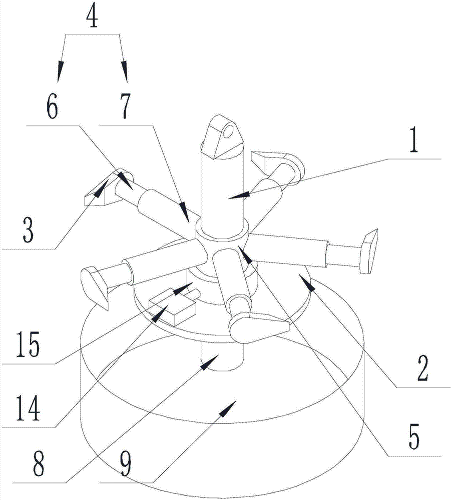
[0030] Such as Figure 1-Figure 4 As shown, the oil well dewaxing device for oil drilling of the present invention includes a suspension device and a wax removal assembly connected in sequence, the suspension device drives the wax removal assembly to move vertically, and the wax removal assembly includes a connecting shaft 1, a support plate 2. The scraper assembly and the driving device, one end of the connecting shaft 1 is connected to the suspension device, the other end of the connecting shaft 1 is connected to the support plate 2, the driving device is located on the upper surface of the support plate 2, and is connected to the scraper assembly , the driving device drives the scraper assembly to rotate along the axis of the connecting shaft 1 .

[0031] The scraper assembly includes a scraper 3, a connecting rod 4 and a drum 5 connected in sequence, one end of the connecting rod 4 is connected to the scraper 3, the blade of the scraper 3 is parallel to the axis of the dru...

Embodiment 2

[0035] The present invention is based on embodiment 1, and the present invention is further described.

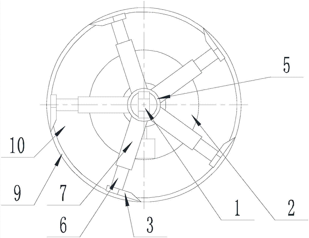
[0036] Such as Figure 1-Figure 4 As shown, in the oil well wax removal device for oil drilling of the present invention, there are five scraper assemblies, and they are evenly arranged on the outer wall of the drum 5 with the axis of the connecting shaft 1 as the center line of symmetry. Setting multiple scraper assemblies can improve wax scraping efficiency and wax scraping effect.

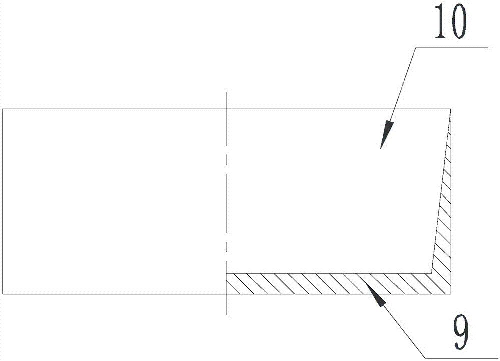
[0037] Further, on the lower surface of the support plate 2, a support rod 8 coaxial with each other and a receiving tray 9 are arranged, the support rod 8 is coaxial with the connecting shaft 1, and one end of the support rod 8 is connected to the end of the support plate 2. The lower surface is connected, and the other end of the support rod 8 is connected with the receiving tray 9.

[0038] A groove 10 is arranged on the upper surface of the material receiving tray 9, the groove 10 is co...

Embodiment 3

[0041] The present invention further describes the suspension device on the basis of Embodiment 1.

[0042] Such as Figure 1-Figure 4 As shown, the oil well wax removal device for oil drilling of the present invention, the suspension device includes a fixed wheel 12, a winch 11 and a steel wire rope 12, one end of the steel wire rope 12 is connected to the winch 11, and the other end of the steel wire rope goes around the fixed wheel 12 After connecting with the connecting shaft 1, the winch 11 makes the connecting shaft 1 move along the axis perpendicular to the horizontal plane by retracting and unwinding the wire rope.


PUM


Abstract

The invention discloses an oil well wax removal device for petroleum drilling. The oil well wax removal device comprises a hanging device and a wax removing device which are sequentially connected. The hanging device drives the wax removing device to perpendicularly move. The wax removing device comprises a connecting shaft, a supporting plate, a scraper assembly and a driving device. One end of the connecting shaft is connected with the hanging device, and the other end of the connecting shaft is connected with the supporting plate. The driving device is located on the upper surface of the supporting plate and connected with the scraper assembly. The driving device drives the scraper assembly to rotate around the axis of the connecting shaft. By putting the wax removing assembly into an oil well where wax needs to be removed through the hanging device and then starting the driving device, scraper blades in the scraper assembly scrape away wax on the wall of the oil well, then the negative situations that a crude oil flowing channel is reduced, oil pressure is raised and oil pipes are blocked are avoided, and normal crude oil flowing and smooth crude oil production are ensured.

Description

technical field [0001] The invention relates to wax removal equipment, in particular to an oil well wax removal device for oil drilling. Background technique [0002] Drilling is the project of using mechanical equipment to drill the formation into cylindrical holes with a certain depth. According to the way of rock crushing and the type of tools used, it can be divided into ton drill and rotary drill. [0003] Ton drill, also known as impact drill. The drill bit is sent to the bottom of the well with a wire rope, and the beam mechanism is driven by power, so that one end of the beam moves up and down, and the wire rope and the drill bit are driven to produce an up and down impact to break the rock. The drilling speed of sudden drilling is slow, the efficiency is low, and it cannot adapt to the drilling requirements of increasing well depth and complex formations, and is gradually replaced by rotary drilling. But it has the advantages of simple equipment, low cost, no pol...

Claims


Application Information

Patent Timeline
Patent Type & Authority Applications(China)
IPC IPC(8): E21B37/00E21B37/02
CPCE21B37/00E21B37/02
Inventor 贺昶明
Owner SICHUAN XILIN OIL SUPPLIES EQUIP
Why Eureka
Try Eureka