High-power LED optical path heat dissipation combined system

A combination system and heat dissipation system technology, applied in the field of high-power LED optical path and liquid-cooled air-cooled heat dissipation combination system, can solve the problems of high energy consumption and limited heat dissipation efficiency, achieve high light efficiency, save space, and reduce design costs.

Active Publication Date: 2017-08-25
HUNAN MINGHE OPTO TECH
View PDF12 Cites 23 Cited by
  • Summary
  • Abstract
  • Description
  • Claims
  • Application Information

AI Technical Summary

Problems solved by technology

[0011] Compared with the traditional air-cooled heat dissipation system, the high-power LED liquid-cooled heat dissipation system disclosed in the above reference document 3 has improved heat dissipation efficiency, but the energy consumption is also higher
Moreover, the liquid cooling system provided in this reference document only has a heat sink module, which can conduct the heat of the LED to the inside of the heat sink, and take away the heat under the action of circulating water. For high-power LEDs, other Cooling efficiency is still limited

Method used


Image

  • High-power LED optical path heat dissipation combined system
  • High-power LED optical path heat dissipation combined system
  • High-power LED optical path heat dissipation combined system

Examples


Embodiment 1

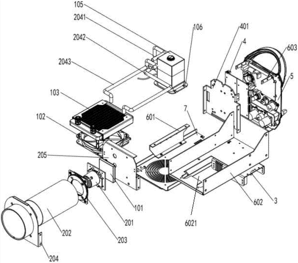
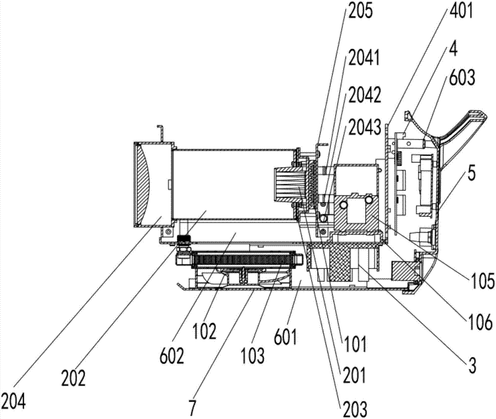
[0090] like Figure 1-9 As shown, this embodiment provides a high-power LED optical path heat dissipation combined system, including an optical path system and a heat dissipation system;

[0091] The heat dissipation system is a liquid-cooled and air-cooled combined heat dissipation system, which specifically includes: a heat absorbing device 101, a fan 102, a liquid-cooled radiator 103, a liquid-cooled pipeline 104, and a liquid circulation pump 105;

[0092] The inside of the heat absorbing device 101 in this embodiment is a hollow structure with diversion grooves, and the heat absorbing device inlet port 106 and the heat absorbing device outlet port 107 are arranged on the outside; it specifically includes: the heat absorbing device main body 1011 and a cover plate 1013, a sealing ring 1012 is arranged between the heat absorbing device main body 1011 and the cover plate 1013 and is fixedly connected by screws 1015, and a heat absorbing device liquid inlet port 1016 and a he...

Embodiment 2

[0121] like Figure 10-12 As shown, the difference between this embodiment and embodiment 1 is:

[0122] When the circulation pipeline 1033 adopts metal pipes such as aluminum pipes or copper pipes, it can be set as follows according to actual needs Figure 10 Metal circulation pipes of different shapes as shown; or, combined pipes with metal pipes or circulation lines embedded with profiled radiators.

[0123] The groove cylinder 10131 inside the cover plate 1013 of the heat absorbing device 101 in Embodiment 1 can also be set as an annular guide groove 10131 ′, and the boss cylinder 10111 in the heat absorbing device main body 1011 and the annular guide groove inside the cover plate 1013 The flow channels 10131' form interconnected flow channels. On the one hand, the boss cylinder 10111 and the annular diversion groove 10131' can increase the heat dissipation area in the cavity; on the other hand, the superconducting liquid can be shunted, so that the superconducting liqui...


PUM


Abstract

The invention provides a high-power LED optical path heat dissipation combined system. The system comprises an optical path system and a heat dissipation system; the heat dissipation system is a liquid cooling and air cooling combined heat dissipation system, and specifically comprises a heat absorbing device, a liquid cooling radiator, a fan, liquid cooling pipelines and a liquid circulating pump; the fan is fixedly mounted at the bottom of the liquid cooling radiator to form a liquid cooling and air cooling heat dissipation module; and the liquid circulating pump, the heat absorbing device and the liquid cooling radiator are connected through multiple liquid cooling pipelines to form a closed circulating loop. The liquid cooling heat dissipation system is applied to cool an LED light source, and is combined with the air cooling heat dissipation system to cool the LED light source, so that the heat dissipation efficiency can be improved, meanwhile, the space can be saved to a greater extent, and the design cost is reduced; and the system has the characteristics of convenience in disassembly and maintenance, high optical effect, low cost, excellent heat dissipation capacity and long service life.

Description

technical field [0001] The invention relates to the technical field of high-power LED optical path heat dissipation, in particular to a high-power LED optical path heat dissipation combined system, and in particular to a high-power LED optical path and liquid-cooled air-cooled heat dissipation combined system. Background technique [0002] As a new type of solid-state cold light source, LED has the advantages of small size, long life, high luminous efficiency, energy saving and environmental protection. High-power LED is one of the hot spots of research and application in recent years, especially after the emergence of high-power LED chips, high-power LED is used in the field of lighting and has a tendency to replace traditional lighting. But at present, LED still faces problems in drive power design, optical path design and heat dissipation design. [0003] In terms of heat dissipation, the heat transfer of high-power LED light sources is the heat transfer process of subst...

Claims


Application Information

Patent Timeline
Patent Type & Authority Applications(China)
IPC IPC(8): F21V29/57F21V29/67F21V29/61F21V15/00F21V29/76F21V29/89F21V29/87F21V29/70F21V29/51F21Y115/10
CPCF21V15/00F21V29/51F21V29/57F21V29/61F21V29/67F21V29/70F21V29/76F21V29/87F21V29/89F21Y2115/10
Inventor 杨勉傅高武傅高鹏
Owner HUNAN MINGHE OPTO TECH
Why Eureka
Try Eureka