Method for manufacturing anti-fogging films of lenses and light hardening device for anti-fogging films of lenses
A thin-film manufacturing method and light-hardening technology, which are applied to devices for coating liquid on the surface, spraying devices, spray booths, etc., can solve the problems of time-consuming operation, bulky volume, and increased production costs, and achieve improved quality stability and reduced Plant area, the effect of improving production efficiency
- Summary
- Abstract
- Description
- Claims
- Application Information
AI Technical Summary
Problems solved by technology
Method used
Image
Examples
no. 1 example
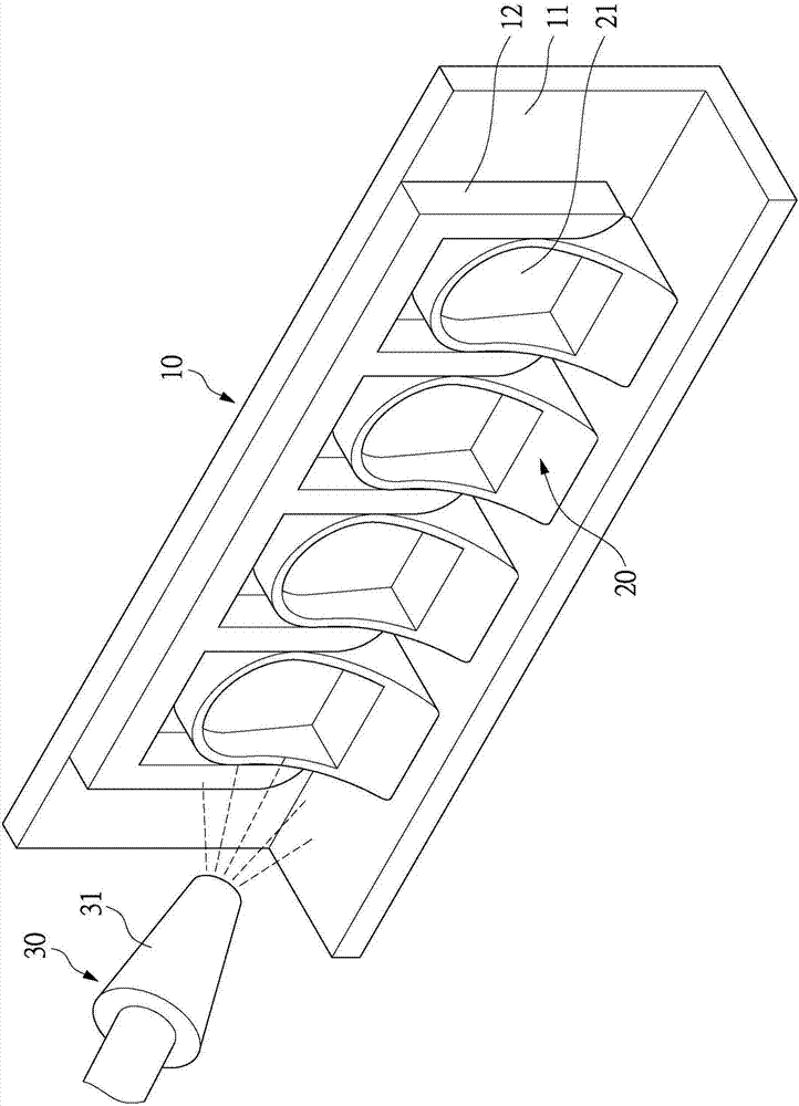
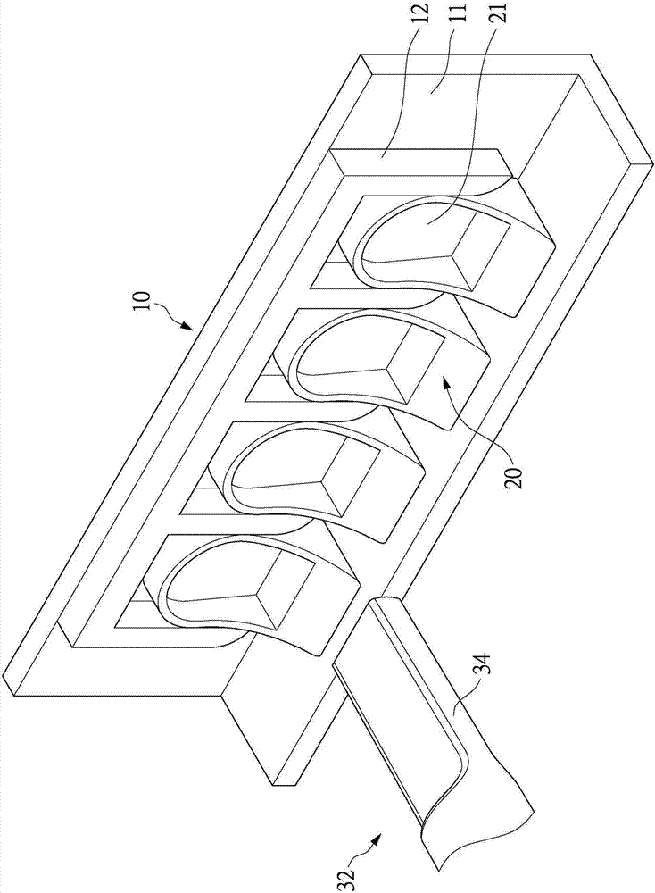
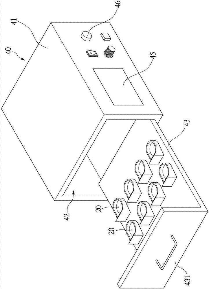
[0083] see Figure 1 to Figure 5 As shown, the lens anti-fog film manufacturing method of the present invention improves on the prior art, adopts ultraviolet light curing technology instead, and adopts the arrangement of the anti-fog film manufacturing unit 60 of the unitary production mode, so as to reduce the use of workshop area and improve Production efficiency, and the purpose of improving quality stability.
[0084] Please refer to Figure 5 and Image 6 As shown, the lens antifogging film manufacturing method of the present invention is used to form an antifogging film on a plastic injection molded lens. The manufacturing method of the present invention includes: a lens loading step S1, a lens spraying step S2, a suction wipe Step S3, a lens pre-drying step S4, a film hardening step S5 and a lens taking step S6. and please also refer to Figure 4 As shown, the above-mentioned lens loading step S1, lens spraying step S2, suction wiping step S3, lens pre-drying step S...
no. 2 example
[0114] like Figure 7 and Figure 8 Shown is the second embodiment of the photohardening device used in the present invention. In this embodiment, the photohardening device 40A includes: an isolation box 41A, and a sealable accommodating space is formed inside the isolation box 41A. One or more sets of ultraviolet light emitting devices 44A are arranged in the accommodating space, and an opening 42A is arranged on one side of the isolation box 41A, and an openable cover 43A is arranged at the opening 42A for the operator Open the opening 42A of the isolation box 41A to perform the operation of placing the lens 20 in the isolation box 41A. After the lens 20 is placed inside the isolation box 41A, multiple groups of ultraviolet light emitting devices 44A can generate ultraviolet light to irradiate the plurality of lenses 20 accommodated on each mobile carrier 10, and make the plurality of lenses 20 on the plurality of lenses 20 The sprayed light-hardening film coating absorbs ...
no. 3 example
[0117] like Figure 9 and Figure 10 Shown is the third embodiment of the light curing device 40B of the present invention. In the third embodiment, the light curing device 40B has an isolation box 41B and a conveyor belt device 47B. The two sides of the isolation box 41B respectively have an inlet 42B and an outlet 43B, and the conveyor belt device 47B is arranged under the isolation box 41B, and penetrates into the interior of the isolation box 41B from the inlet 42B of the isolation box 41B. , and pass through the outlet 43B to the outside of the isolation box 41B.
[0118]A plurality of lenses 20 can be placed on the conveyor belt device 47B, so the plurality of lenses 20 can be transported through the inner side of the isolation box 41B through the conveyor belt device 47B. The inner side of the isolation box 41B is also provided with a plurality of ultraviolet light emitting devices 44B. When a plurality of lenses 20 pass through the isolation box 41B, the lenses 20 ca...
PUM
 Abstract
Description
Claims
Application Information
 - R&D
- Intellectual Property
- Life Sciences
- Materials
- Tech Scout
- Unparalleled Data Quality
- Higher Quality Content
- 60% Fewer Hallucinations
Browse by: Latest US Patents, China's latest patents, Technical Efficacy Thesaurus, Application Domain, Technology Topic, Popular Technical Reports.
© 2025 PatSnap. All rights reserved.Legal|Privacy policy|Modern Slavery Act Transparency Statement|Sitemap|About US| Contact US: help@patsnap.com


