

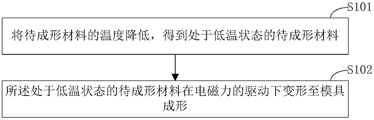
An electromagnetic forming method and device based on low temperature conditions
A technology of electromagnetic forming and low temperature conditions, applied in forming tools, metal processing equipment, manufacturing tools, etc., can solve the problems of limited forming force forming coils, large temperature rise of forming coils, reducing production efficiency, etc., to improve electrical conductivity, The effect of improving the forming force and improving the production efficiency
- Summary
- Abstract
- Description
- Claims
- Application Information
AI Technical Summary
Problems solved by technology
Method used
Image

Examples
Embodiment 1
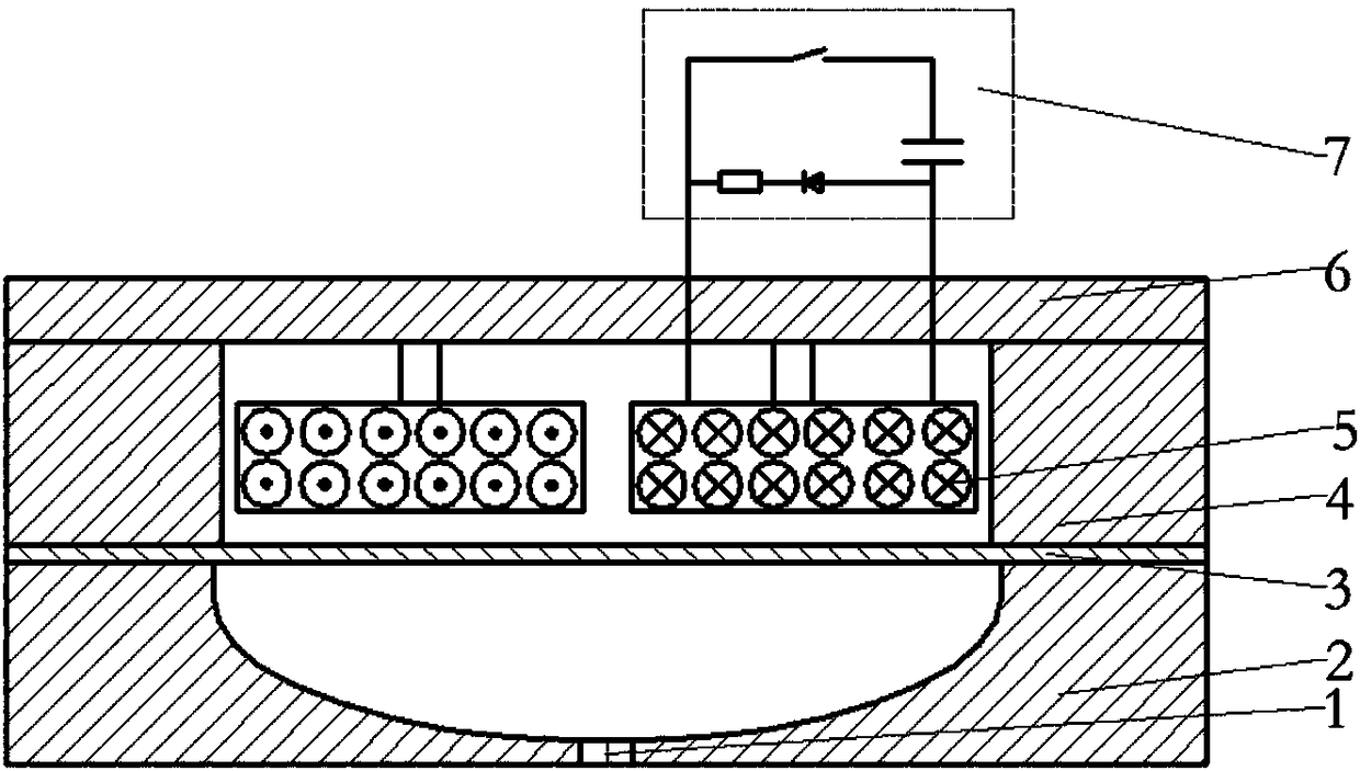
[0049] image 3 A structural schematic diagram of an electromagnetic forming device provided for an embodiment of the present invention, such as image 3 As shown, it includes: a die 2, a blank holder 4, a forming coil 5, a forming coil fixing plate 6 and a capacitive pulse power supply 7 with a freewheeling circuit.
[0050] The die 2 is used to carry the material 3 to be formed, and the material to be formed is in a low temperature state. The blank holder 3 is arranged on the upper end of the die 2, and is used to provide the blank holder force for the flange area of the material 3 to be formed, so as to prevent the peripheral area of the material to be formed from excessive flow and cause wrinkling failure during the forming process. The forming coil fixing plate 6 is arranged on the upper end of the blank holder 4 for fixing the forming coil. The forming coil 5 is arranged inside the area surrounded by the material 3 to be formed, the blank holder 4 and the fixing pl...
Embodiment 2
[0066] Figure 5 A structural schematic diagram of another electromagnetic forming device provided for an embodiment of the present invention, such as Figure 5 As shown, it includes: a die 2, a blank holder 4, a forming coil 5, a forming coil fixing plate 6 and a capacitive pulse power supply 7 with a freewheeling circuit.
[0067] The side of the lower end of the blank holder 4 in contact with the material 3 to be formed is provided with n annular circulation channels, and the n annular circulation channels communicate with the area surrounded by the material 3 to be formed, the blank holder 4 and the forming coil fixing plate 6, and the forming coil The fixing plate 6 is provided with a through hole 9, and n is an integer greater than 0. The blank holder 4 is also used to hold the cooling medium 8 .
[0068] The through holes on the forming coil fixing plate 6 are used to allow the cooling medium 8 to flow into the blank holder 4, so that the cooling medium 8 reduces the ...
Embodiment 3
[0077] Figure 7 A structural schematic diagram of another electromagnetic forming device provided for an embodiment of the present invention, such as Figure 7 As shown, it includes: a die 2, a blank holder 4 that can contain a cooling medium, a forming coil 5, a forming coil fixing plate 6, and a capacitive pulse power supply 7 with a freewheeling circuit. The lower end surface of the blank holder 4 is in contact with the workpiece blank or semi-finished product and has a circulation channel 10. When liquid nitrogen passes through the circulation channel 10, the workpiece blank or semi-finished product 3 will be cooled by the principle of heat transfer.
[0078] The side of the lower end of the blank holder 4 in contact with the material 3 to be formed is provided with n annular circulation channels, and the n annular circulation channels are not connected to the area surrounded by the material 3 to be formed, the blank holder 4 and the forming coil fixing plate 6 , the for...
PUM
 Abstract
Description
Claims
Application Information