Sticky slag separator for molten iron tank and preparation method

A technology for molten iron tanks and breakers, which is applied in the direction of manufacturing tools, casting equipment, metal processing equipment, etc., can solve the problems of reducing the cost of castable preparation, difficulty in popularization and application, and easy damage, so as to avoid floating and loosening of slag breakers, Structure and size optimization to ensure continuous and stable results

Active Publication Date: 2019-06-18
武汉钢铁有限公司
View PDF10 Cites 0 Cited by
  • Summary
  • Abstract
  • Description
  • Claims
  • Application Information

AI Technical Summary

Problems solved by technology

Aiming at the problem that the brick refractory lining of the tank mouth is easy to be damaged during the removal of the bonding circle of the molten iron tank, the Chinese patent "Ouyang Degang, Wang Qingfang, Jiang Yanghu, etc., a steel fiber reinforced refractory castable along the edge of the desulfurized molten iron tank, patent number : ZL200810048976.0" discloses a tank edge castable with refractory recycled material as the main raw material, through the compounding of refractory recycled material and refractory mineral raw materials, the performance of the castable can be guaranteed, and the cost of castable preparation can be greatly reduced. The use of regenerated aluminum silicate fiber and regenerated heat-resistant steel fiber can improve the thermal shock stability of castables and improve the resistance to mechanical damage of castables. Good application results have been achieved in production, but due to the large differences in the size of molten iron tanks, the height of free space at the mouth of the tank when it is fully loaded, the temperature of molten iron, and the amount of slag on the molten iron level in different iron and steel enterprises, no specific implementation method has been provided for how to use it, resulting in Difficulty in promotion and application

Method used


Image

  • Sticky slag separator for molten iron tank and preparation method
  • Sticky slag separator for molten iron tank and preparation method
  • Sticky slag separator for molten iron tank and preparation method

Examples


Embodiment Construction

[0035] The present invention will be further described in detail below in conjunction with the accompanying drawings and specific embodiments.

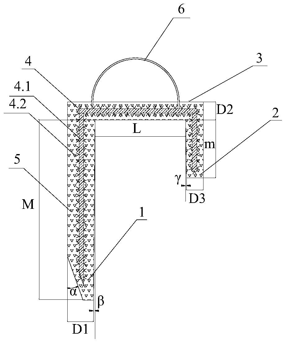
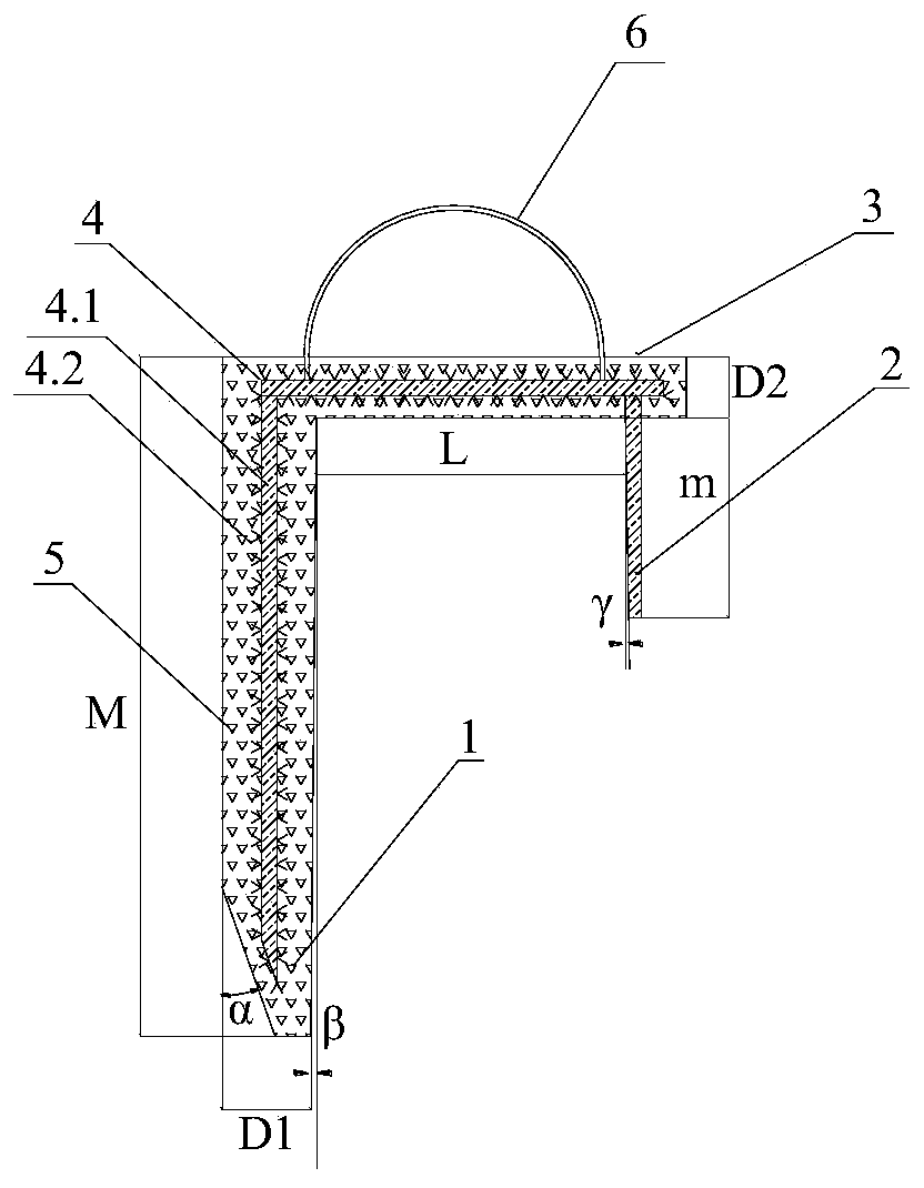
[0036] Such as figure 1 The sticky slag breaker for the ladle includes a beam 3, a long leg 1 vertically connected to one end of the beam 3, and a short leg 2 vertically connected to the other end of the beam 3, forming a π-shaped breaker. The beam 3, the long leg 1 and the short leg 2 are all composed of a steel core component 4 wrapped by a refractory castable lining 5, and the steel core component 4 is composed of threaded steel bars or steel pipes or flat steel 4.1 welded with a V-shaped metal anchor 4.2; of course, The long leg 1, the crossbeam 3 and the short leg 2 can all be directly formed by the steel core assembly 4. When the short leg 2 is directly formed by the steel core assembly 4, the steel core assembly 4 of the short leg 2 is not welded with the V-shaped metal anchor piece 5, Such as figure 2 shown. Through the st...


PUM

PropertyMeasurementUnit
thicknessaaaaaaaaaa
lengthaaaaaaaaaa
thicknessaaaaaaaaaa

Abstract

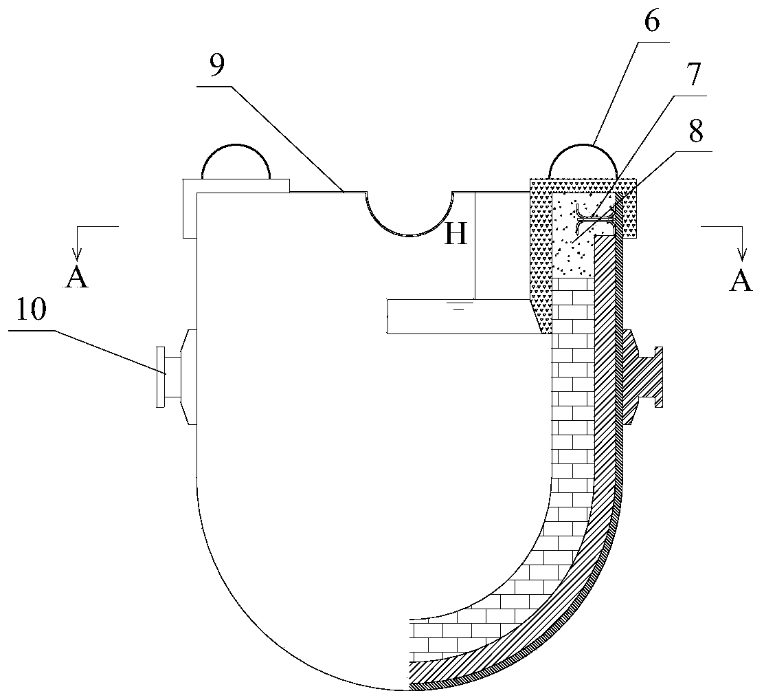
The invention discloses an adhered slag partition device for a molten iron tank. The device comprises a beam, a long leg perpendicularly connected to one end of the beam and a short leg perpendicularly connected to the other end of the beam, and the beam, the long leg and the short leg are formed by means of the method that fire-resistant pouring material liners wrap steel core assemblies; through structural design of a pi-shaped component composed of the beam, the short leg and the long leg, on-site mounting and fixing of the slag partition device are facilitated, and it is ensured that the efficacy that an adhered substance ring is partitioned by the slag partition device in the operation process of the molten iron tank is exerted; and the length M of the long leg is 50-200 mm larger than the height H from the molten iron liquid level to the top face of a tank port during the rated loading capacity of the molten iron tank, the portion, entering the molten iron section, of the outer side face of the long leg inwards inclines by the angle alpha of 10-15 degrees, thorough partition of the adhered substance ring of the tank port of the molten iron tank by the slag partition device is achieved, and the effective volume of the molten iron tank is ensured.

Description

technical field [0001] The invention belongs to the technical field of iron and steel metallurgy refractory materials, and in particular relates to a sticky slag breaker for a molten iron tank and a preparation method thereof. Background technique [0002] The hot metal tank is the molten iron container for the large-scale and stable transportation of molten iron in the iron and steel complex. It is the molten metal logistics channel between the ironmaking and steelmaking processes. Therefore, it is an important part of the production line of the iron and steel enterprises. An important guarantee for normal and stable production. However, during the transportation of molten iron, due to the heat dissipation between the tank mouth and the tank wall and the shaking of the molten iron tank, the molten iron and molten slag on the refractory wall surface of the molten iron tank permeate, condense and adhere to form a hard bond of slag and iron that is firmly bonded. At the same ...

Claims


Application Information

Patent Timeline
Patent Type & Authority Patents(China)
IPC IPC(8): B22D41/00C04B35/66
CPCB22D41/00C04B35/66C04B2235/3217C04B2235/3418C04B2235/3463C04B2235/349C04B2235/3826C04B2235/447C04B2235/5228
Inventor 欧阳德刚吴浩周甫刘凯李明晖沈继胜
Owner 武汉钢铁有限公司
Why Eureka
Try Eureka