Automatic temperature rise control device for crankshaft and bearing bushes of mechanical press

An automatic control device and a technology of a mechanical press, which is applied in the field of mechanical presses, can solve the problems of reducing the motion accuracy of the crankshaft and the precision of the mechanical press, grinding, and accelerated wear of bearing bushes, so as to avoid rapid wear or strain, and control temperature High degree of automation, improving the effect of sliding friction environment

Active Publication Date: 2017-08-29
RONGCHENG HUADONG METAL FORMING MACHINERY
View PDF7 Cites 19 Cited by
  • Summary
  • Abstract
  • Description
  • Claims
  • Application Information

AI Technical Summary

Problems solved by technology

[0004] There is sliding friction between the crankshaft and the bearing bush. When the crankshaft rotates rapidly and continuously for a long time, it will generate friction and heat. The gap between the crankshaft and the bearing bush will decrease, and the wear degree of the bearing bush will increase, which will further accelerate the wear of the bearing bush, and even cause the bearing bush to be damaged. Or maintenance affects production
Sometimes in order to avoid wear and tear, in the design and manufacture, the clearance of the thermal expansion of the crankshaft and the bearing bush is reserved in advance, but this will inevitably reduce the precision of the crankshaft movement and the precision of the mechanical press.
Or generally increase the oil supply to reduce the friction coefficient between the crankshaft and the bearing bush. Although the increase in oil can indirectly reduce part of the heat, a large amount of oil is likely to cause waste, pollute the environment, and increase the work for workers to clean up the oil. quantity
None of the above technical solutions can fundamentally solve the problem of continuous temperature rise caused by the high-speed rotation of the crankshaft and bearing bush

Method used


Image

  • Automatic temperature rise control device for crankshaft and bearing bushes of mechanical press
  • Automatic temperature rise control device for crankshaft and bearing bushes of mechanical press
  • Automatic temperature rise control device for crankshaft and bearing bushes of mechanical press

Examples


Embodiment Construction

[0031] In order to clearly illustrate the technical features of this solution, the present invention will be described in detail below through specific implementation modes and in conjunction with the accompanying drawings.

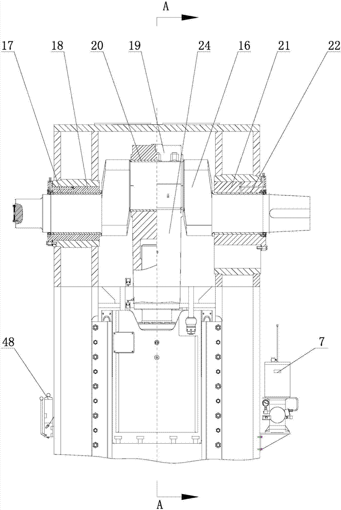
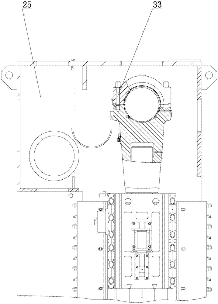
[0032] Such as Figure 3-10As shown, the automatic control device for crankshaft and bearing bush temperature rise of a mechanical press includes a fuselage 25, a crankshaft 16, a first support sleeve 18, a second support sleeve 21, a connecting rod cover 19 and a connecting rod 24, the first support sleeve 18 and The first shaft end bearing bush 17 and the second shaft end bearing bush 22 are respectively arranged between the second support sleeve 21 and the crankshaft 16, the connecting rod cover 19 and the connecting rod 24 are fixedly connected by a double-ended screw 33 and a nut 34, and the crankshaft 16 is connected to the connecting rod. A connecting rod tile 20 is provided between the rod 24 and the connecting rod cover 19, and a gas circuit temp...


PUM


Abstract

An automatic temperature rise control device for a crankshaft and bearing bushes of a mechanical press comprises a machine body, the crankshaft, a first supporting sleeve, a second supporting sleeve, a connecting rod cover, a connecting rod, a first shaft end bearing bush, a second shaft end bearing bush and a connecting rod bush; an air circuit temperature control system and a temperature detection and control system are arranged on the machine body; the air circuit temperature control system comprises an air cooling machine arranged on the machine body; the air cooling machine is connected with an air distributor; the air distributor communicates with spiral grooves formed in inner walls of the first supporting sleeve, the second supporting sleeve, the connecting rod cover and the connecting rod through multiple air inlet pipes; the temperature detection and control system comprises a controller and multiple temperature sensors for detecting the temperatures of the first shaft end bearing bush, the second shaft end bearing bush and the connecting rod bush; the temperature sensors are connected with the controller through circuits; and the controller is connected with the air cooling machine through a circuit. The control device has the advantages that the working temperature of the bearing bushes is automatically controlled, the design clearance is reduced, the service life of the crankshaft and the service life of the bearing bushes are prolonged, the operation speed and precision of the crankshaft is improved, the production efficiency is high, the product quality is high, and the like.

Description

Technical field: [0001] The invention relates to the technical field of mechanical presses, in particular to an automatic control device for temperature rise of crankshafts and bearing bushes of mechanical presses. Background technique: [0002] Such as Figure 1-2 As shown, the relative motion between the crankshaft of the existing crankshaft-type mechanical press and the bearing pad at the shaft end and the connecting rod pad is a sliding friction pair, and the bearing pad at the shaft end and the connecting rod pad are generally collectively referred to as the bearing pad. The bearing bush at the shaft end adopts manual multi-point grease lubrication pump to manually lubricate as needed, and the connecting rod bush adopts electric grease lubrication pump and quantitative distributor to automatically supply oil intermittently according to the setting. Lubricating machines with low mechanical performance requirements can basically meet the requirements, but cannot meet the ...

Claims


Application Information

Patent Timeline
Patent Type & Authority Applications(China)
IPC IPC(8): B30B15/14B30B15/00B30B1/26
CPCB30B1/26B30B15/00B30B15/0088B30B15/148
Inventor 邱玉良郝玉琴彭鑫亮周红波宋晓龙王鹏波
Owner RONGCHENG HUADONG METAL FORMING MACHINERY
Why Eureka
Try Eureka