Combined steel box girder for high-speed railways and construction method thereof

A technology for high-speed railways and construction methods, applied in bridge construction, construction, bridges, etc., can solve problems such as increased hoisting weight, complex on-site operations, and increased operating time, and achieves the characteristics of ensuring dynamic stability, facilitating hoisting operations, and increasing spans Effect

Active Publication Date: 2017-08-29
ZHENGZHOU UNIV
View PDF7 Cites 14 Cited by
  • Summary
  • Abstract
  • Description
  • Claims
  • Application Information

AI Technical Summary

Problems solved by technology

If prestress is applied to the concrete after pouring, due to the existence of the steel floor, only part of the applied prestress acts on the concrete slab, and as the concrete shrinks and creeps, the prestress in the concrete will gradually decrease, which is an inefficient method, and it is still possible to use cracking under load
Another solution is to use a steel box as the bottom plate of the steel box girder, pour concrete or mortar into the interior, and then apply prestress. This is a good method and can meet engineering applications, but there are still the following disadvantages: Most of it is "consumed" on the steel box, and the steel box has a strong tensile capacity, so this part of the prestress is not need

Method used


Image

  • Combined steel box girder for high-speed railways and construction method thereof
  • Combined steel box girder for high-speed railways and construction method thereof
  • Combined steel box girder for high-speed railways and construction method thereof

Examples


Embodiment 1

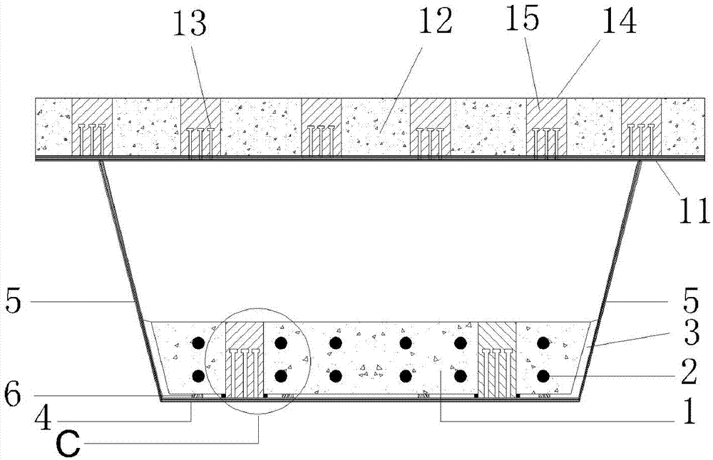
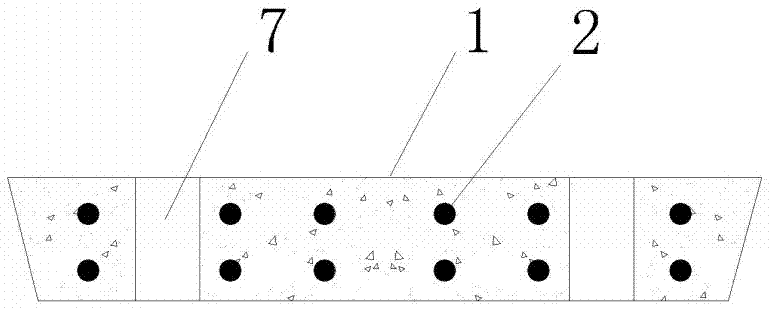
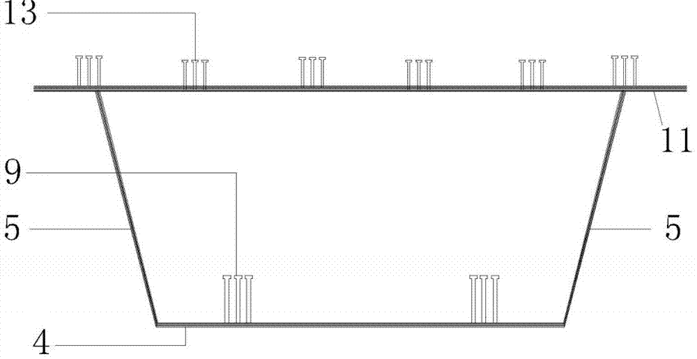
[0038] For the schematic diagram corresponding to this embodiment, see figure 1 , figure 2 , image 3 and Figure 4 . This embodiment is applied to the manufacture and installation of high-speed railway bridges. The steel box in the present invention is composed of a web (5), a steel bottom plate (4) and an upper flange plate (11), and there are upper truss-type diaphragms arranged at a certain distance in the longitudinal direction inside. A prestressed concrete slab (1) is installed inside the steel box, an adhesive layer (3) is arranged between the two, and prestressed tendons (2) are arranged in the prestressed concrete slab (1). A prefabricated concrete roof (12) is connected to the upper flange plate (11), and the two are connected by roof shear nail groups (13) welded on the upper surface of the upper flange plate (11). Correspondingly, a rectangular roof shear groove (14) is reserved on the concrete roof (12), and the roof micro-expansion concrete (15) is poured th...

Embodiment 2

[0046] For the schematic diagram corresponding to this embodiment, see Figure 5 . This embodiment is a modification of Embodiment 1, changing the connection method between the prestressed concrete slab (1) and the steel floor (4). Screw rods (19) are welded on the upper surface of the steel base plate (4), and correspondingly, when the prefabricated prestressed concrete slab (1) is prefabricated, vertical cavities are reserved at corresponding positions thereon. After the prestressed concrete slab (1) is installed, the screw rod (19) is successively installed with a lower backing plate (16), an upper backing plate (17) and a nut (18) from bottom to top. Before the prestressed concrete slab (1) is installed, the lower backing plate (16) is installed earlier, and then the rubber pad is overcoated on the screw rod (19), and falls to the lower backing plate (16) upper surface.

Embodiment 3

[0048] The schematic diagram corresponding to this embodiment is shown in Figure 6 . This embodiment is a modification of the previous embodiment. The concrete roof (12) is constructed by the cast-in-place method. The upper surface of the upper flange plate (11) is welded with shear studs (20). Correspondingly, the step (b) in the construction method is omitted, and the installation of the prefabricated concrete roof (12) in the step (d) is replaced by on-site pouring. This embodiment reduces the workload of prefabrication and installation, but needs to strengthen on-site quality management and correspondingly increases the construction time.


PUM


Abstract

The invention discloses a combined steel box girder for high-speed railways and a construction method thereof, belonging to the field of high speed railway bridges. A top flange plate of the steel box of the combined steel box girder is provided with a shearing resistance connecting member which connects the above concrete slabs with the top flange plate. At the same time, a steel base plate and a prefabricated prestressed concrete plate are combined to collectively act as the base plate of the combined steel box girder for jointly bearing stress. Concrete slabs on the top flange plate can be cast in situ or prefabricated. since the girder which is made of the steel box, the concrete top plate and the prestressed concrete plate inside the steel box can be assembled in site, which is convenient for transmission and hoisting and it is possible to build longer span simply supported girder bridges on land. Compared with present whole simple girders of the same span, the provided combined steel box girder has increased cross section rigidity of the steel box girder, the weight of girders is reduced and the span of girders is increased. The combined steel box girder of the invention has reasonable construction stress and is convenient to construct; technical support is provided for building longer span simply supported girder bridges on land.

Description

technical field [0001] The invention relates to a combined steel box girder for high-speed railways and a construction method thereof, belonging to the field of high-speed railway bridges. Background technique [0002] At present, in the field of high-speed railways, simply supported beam bridges mostly use T-shaped section beams or box-shaped section beams. The former is referred to as T-beam and the latter is referred to as box girder. Because the T-beam bridge composed of T-beams has small lateral stiffness, poor torsion resistance, and poor stability during installation, the on-site operation time is long, so it is not suitable for use with large spans. Simply supported girder bridges with longer spans generally use box girders. [0003] Box girders include concrete box girders, steel box girders and composite steel box girders. When the span is large, the weight of the concrete box girder is very heavy, which brings difficulty to pouring or erection. For example, a 32...

Claims


Application Information

Patent Timeline
IPC IPC(8): E01D19/00E01D2/04E01D21/00E01D101/30
Inventor 魏建东
Owner ZHENGZHOU UNIV
Why Eureka
Try Eureka