Vacuum glass and construction door using vacuum glass

A technology of vacuum glass and glass, which is applied to buildings, building components, sustainable buildings, etc. It can solve the problems of troublesome construction, high cost, and opacity of ceramic points, and achieve the advantages of easy vacuuming, enhanced support force, and increased lighting rate Effect

Inactive Publication Date: 2017-08-29
成立
View PDF4 Cites 3 Cited by
  • Summary
  • Abstract
  • Description
  • Claims
  • Application Information

AI Technical Summary

Problems solved by technology

[0002] At present, the vacuum glass is double-layer glass, and the cavity between the double-layer glass is evacuated to enhance the heat insulation effect of the double-layer glass. During the process, the double-layer glass is easy to burst. In order to solve this problem, a supporting ceramic point is added between the existing double-layer vacuum glass to enhance the compressive capacity.
However, ceramic dots are opaque, which affects the light transmittance of the double-layer glass, and the construction is troublesome, resulting in high cost, and cannot achieve dimming.
With the development of science and technology and the improvement of people's living standards, the existing double-layer vacuum glass with this structure is difficult to meet the requirements

Method used


Image

  • Vacuum glass and construction door using vacuum glass
  • Vacuum glass and construction door using vacuum glass
  • Vacuum glass and construction door using vacuum glass

Examples


Embodiment 1

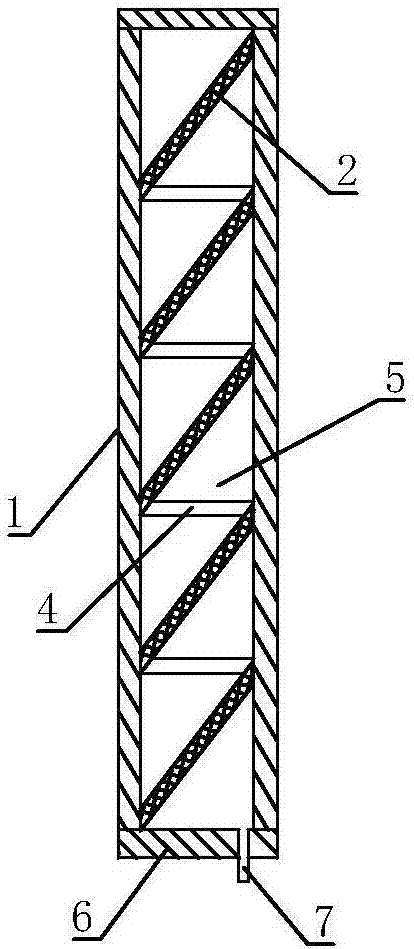
[0036] refer to figure 1 and figure 2 , the vacuum glass of the present embodiment comprises two oppositely arranged main glass plates 1, a side plate 6 is connected between each side of the two main glass plates 1, and the main glass plate 1 and the side plates 6 jointly form a glass lumen. A one-way valve 7 for evacuating the glass inner cavity is provided on the main glass plate 1 or on the side plate 6 .

[0037] The outside of the joint between the main glass plate 1 and the side plate 6 is coated with a sealant to increase the overall pressure bearing capacity of the vacuum glass.

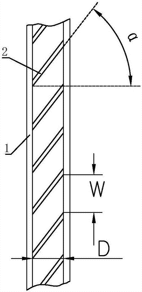
[0038] Multiple layers of first supporting layers 2 are arranged in parallel at intervals in the glass cavity, and each layer of first supporting layers 2 extends obliquely downward from the inner surface of the main glass plate 1 on one side to the inner surface of the main glass plate 1 on the other side, correspondingly A light-transmitting second support layer 4 is laterally connected...

Embodiment 2

[0045]refer to image 3 , the structure of this embodiment is basically the same as that of Embodiment 1, the difference is that:

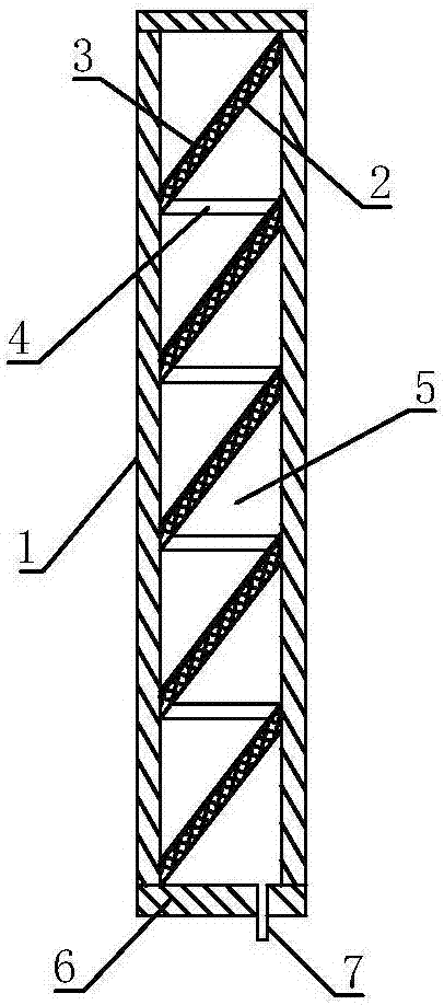
[0046] A solar energy utilization device is fixed on each first supporting layer 2 . The solar energy utilization device shown in this embodiment is a solar battery panel 3 , of course, the solar energy utilization device may also be a solar vacuum heat collecting tube or the like.

Embodiment 3

[0048] refer to Figure 4 The mechanism of this embodiment is basically the same as that of Embodiment 2, except that the second support layer 4 is arranged obliquely, with one end abutting on the upper first support layer 2 and the lower end abutting on the lower first support layer 2 . When one end of the second support layer 4 is in contact with the first support layer 2 and the other end is in contact with the main glass plate 1 on one side, the first support layer 2, the second support layer 4 and the main glass plate 1 jointly form a longitudinal The strong supporting structure with a triangular cross-section greatly enhances the supporting force and makes the vacuum glass stronger as a whole, which can meet the strength and firmness requirements of building blocks, and is suitable for use as building blocks, doors and windows, etc.


PUM


Abstract

The invention discloses a vacuum glass. The vacuum glass comprises two pieces of main glass plates arranged oppositely. Side plates are connected between each side of the two main glass plates. A glass inner cavity is formed by the main glass plates and the side plates. Check valves used for vacuum pumping on the glass inner cavity are arranged on the main glass plates and the side plates. A plurality of first support layers are arranged in the glass inner cavity in parallel and at intervals. Opaque second supports are horizontally connected between two layers of the first support layer in two adjacent layers. The vacuum glass further discloses a construction door using vacuum glass. The vacuum glass is high in support structure strength, and firm in wholeness, the vacuum glass has no influence to translucency, vacuum pumping pressure bearing is guaranteed, and heat insulation effect is good.

Description

technical field [0001] The invention relates to the technical field of vacuum glass, in particular to a vacuum glass and a building door using the vacuum glass. Background technique [0002] At present, the vacuum glass is double-layer glass, and the cavity between the double-layer glass is evacuated to enhance the heat insulation effect of the double-layer glass. During the process, the double-layer glass is easy to burst. In order to solve this problem, supporting ceramic points are added between the existing double-layer vacuum glass to enhance the compressive capacity. However, ceramic dots are opaque, which affects the light transmittance of the double-layer glass, and the construction is troublesome, resulting in high cost, and cannot achieve dimming. With the development of science and technology and the improvement of people's living standards, the existing double-layer vacuum glass with this structure is difficult to meet the requirements. Contents of the inventi...

Claims


Application Information

Patent Timeline
Patent Type & Authority Applications(China)
IPC IPC(8): E06B3/66E06B3/663E06B3/67E06B7/30H02S20/26
CPCE06B3/6612E06B3/663E06B3/6715E06B7/30H02S20/26Y02A30/249Y02B10/10Y02B80/22Y02E10/50
Inventor 成立
Owner 成立
Why Eureka
Try Eureka