Spiral filter and design method thereof

A filter and spiral technology, applied in waveguide devices, electrical components, circuits, etc., can solve the problems of easy deformation of spiral coils and poor device stability, and achieve small size, improved reliability and stability, and operability strong effect

Active Publication Date: 2017-08-29
南京华德通信技术有限公司
View PDF5 Cites 5 Cited by
  • Summary
  • Abstract
  • Description
  • Claims
  • Application Information

AI Technical Summary

Problems solved by technology

Therefore, we wind the resonator into a spiral shape to greatly reduce the overall length of the resonator, but the helical coil is easily deformed, resulting in poor stability of the device

Method used


Image

  • Spiral filter and design method thereof
  • Spiral filter and design method thereof
  • Spiral filter and design method thereof

Examples


Embodiment 1

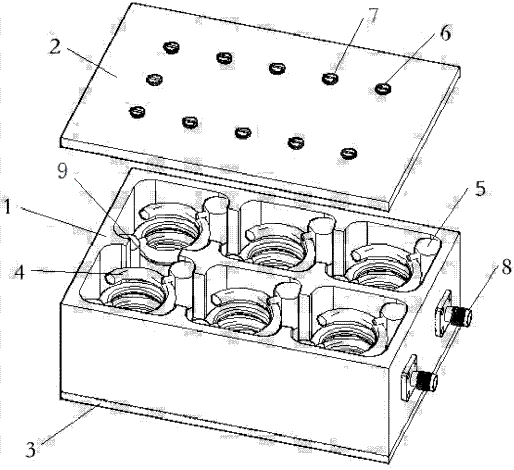
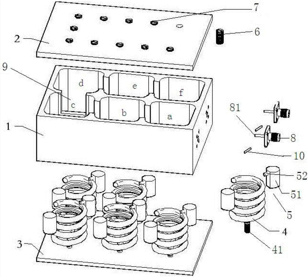
[0040] see figure 1 and figure 2 , the helical filter of this embodiment is a 6-cavity helical filter, and its main components include: a cavity 1, an upper cover plate 2, a lower base plate 3, a spiral resonator 4, a dielectric fixing column 5, a tuning screw 6, and a coupling screw 7 , Connector 8 and connecting wire 10. Among them, the cavity 1, the upper cover plate 2 and the lower base plate 3 are all made of good conductor materials and fixedly connected with screws, and 6 square or rectangular single cavities are formed in the cavity 1, and the single cavities are arranged according to a certain structure or order , two adjacent single cavities communicate through windows 9, and installing a helical resonator 4 in each single cavity constitutes the main body of the helical filter.

[0041] It should be noted that not all adjacent single cavities are provided with windows 9, such as figure 2 As shown, there are six single cavities a, b, c, d, e, f in the cavity 1, a...

Embodiment 2

[0048] The helical filter of this embodiment is such as Figure 4 The working principle of the shown 3-cavity helical filter is roughly similar to that of Embodiment 1, the difference in structure is that the number of single cavities is 3, correspondingly, the number of helical harmonic oscillators 4 is 3, and the number of windows 9 is 2 one, and the rest will not be repeated.

Embodiment 3

[0050] The helical filter of this embodiment is such as Figure 5 The working principle of the 4-cavity helical filter shown is roughly similar to that of Embodiment 1. The difference in structure is that the number of single cavities is 4. Correspondingly, the number of helical harmonic oscillators 4 is 4, and the number of windows 9 is 3. one, and the rest will not be repeated.


PUM


Abstract

The invention discloses a spiral filter and a design method thereof. The spiral filter comprises a cavity, an upper cover plate, a lower base plate, spiral harmonic oscillators, medium fixed columns, tuning screws, coupling screws, a connector and a connecting wire, wherein a plurality of single cavities are formed in the cavity, and every two adjacent single cavities are communicated through a window; the spiral harmonic oscillators are mounted in the single cavities, and the bottoms of the spiral harmonic oscillators are in short-circuited connection with the lower base plate; and the medium fixed columns are arranged in gaps between the spiral harmonic oscillators and the inner walls of the single cavities. The spiral filter disclosed by the invention can be applied to very high frequency (VHF) and ultrahigh frequency (UHF) wave bands, and has the advantage of small size; each single cavity is internally provided with the corresponding medium fixed column, and the spiral harmonic oscillators are effectively prevented from being deformed under the effect of gravity, so that the reliability and stability of the spiral filter are improved; the resonant frequency and coupling coefficient can be quickly and reliably adjusted through the tuning screws and the coupling screws; and moreover, the design method in the invention is high in operability, and can obtain the device meeting the target requirement.

Description

technical field [0001] The invention relates to a microwave device, in particular to a helical filter and a design method thereof, belonging to the technical field of microwave communication. Background technique [0002] The helical filter is named after the use of a helical resonator to realize the parallel resonant circuit in the coupled resonator filter. It has many advantages such as small size, high unloaded Q value, and easy processing. It is a microwave and radio frequency signal transmission system. important device. In the RF microwave frequency band, the size of the device has a great relationship with the frequency of the electromagnetic wave. For example, at a frequency of 100MHz, the wavelength of the electromagnetic wave in the air is about 3000mm. In the design, when the length of the harmonic oscillator is 1 / 4 of the wavelength, it will To achieve a good resonance effect, that is, the length of the resonator is about 750mm. If the filter is designed in this...

Claims


Application Information

Patent Timeline
Patent Type & Authority Applications(China)
IPC IPC(8): H01P1/208H01P11/00
CPCH01P1/208H01P11/007
Inventor 王小雨杨彬周罗通马少华
Owner 南京华德通信技术有限公司
Why Eureka
Try Eureka