
Adaptive slope compensation circuit suitable for controlling buck converter in peak current mode

A peak current and slope compensation technology, applied in the direction of converting DC power input to DC power output, regulating electrical variables, and controlling/regulating systems, etc. It can solve the problems of quantity and other issues, so as to achieve the effect of simple and easy solution, avoiding sub-harmonic oscillation and reducing the load capacity of the system.

Inactive Publication Date: 2017-08-29
UNIV OF ELECTRONIC SCI & TECH OF CHINA
View PDF4 Cites 19 Cited by
  • Summary
  • Abstract
  • Description
  • Claims
  • Application Information

AI Technical Summary

Problems solved by technology

[0003] However, the peak current mode will have sub-harmonic oscillation when the duty cycle is greater than 50%, so a slope compensation circuit is required to increase system stability
The traditional compensation methods include fixed slope compensation and segmented linear compensation. In the case of a wide range of duty ratio changes under different application conditions, excess compensation will occur, resulting in a decrease in system load capacity and poor transient response characteristics.

Method used


Image

  • Adaptive slope compensation circuit suitable for controlling buck converter in peak current mode
  • Adaptive slope compensation circuit suitable for controlling buck converter in peak current mode
  • Adaptive slope compensation circuit suitable for controlling buck converter in peak current mode

Examples


Embodiment Construction

[0024] The technical solution of the present invention will be specifically described below in conjunction with the accompanying drawings and specific embodiments:

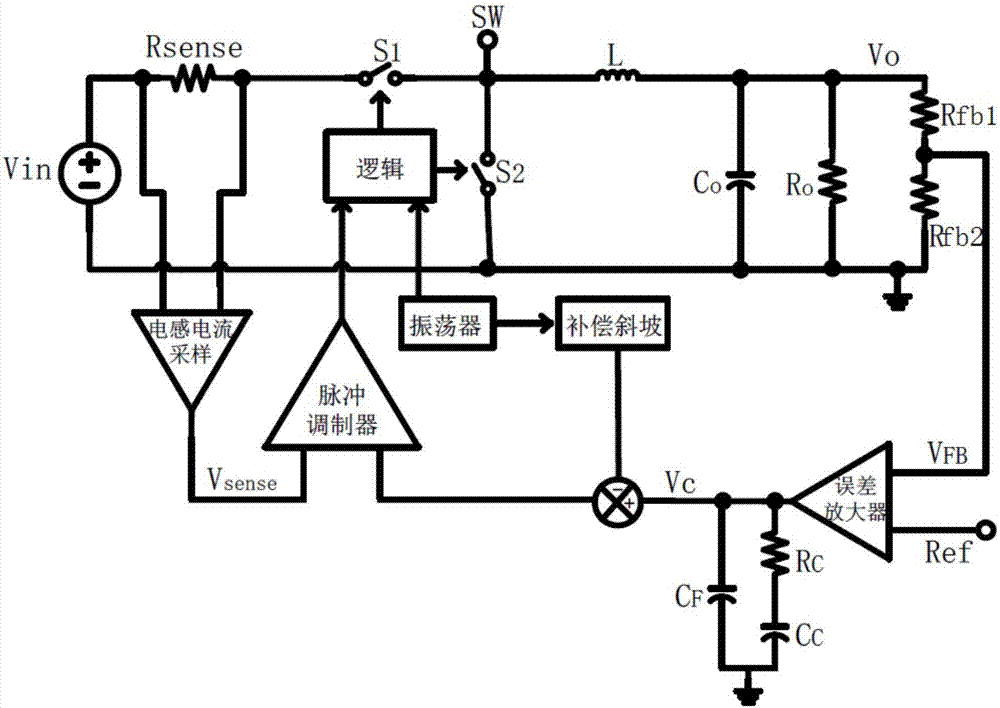
[0025] figure 1 Shown is the schematic control diagram of the peak current mode control type step-down converter loop, which includes the input voltage Vin, the inductor L, the upper and lower power transistors S1 and S2, the output capacitor Co and the output load Ro, and the output voltage is Vo . The time when the upper tube is turned on and the lower tube is turned off is Ton, and the end mark is when the sampling inductor current after the superimposed compensation slope touches the output Vc of the error amplifier (EA). Here, the error amplifier adopts type II compensation, and its compensation network is composed of RC, CC, and CF located at the output end of the error amplifier; the time when the upper tube is turned off and the lower tube is turned on is Toff, because the peak current mode control type s...


PUM


Abstract

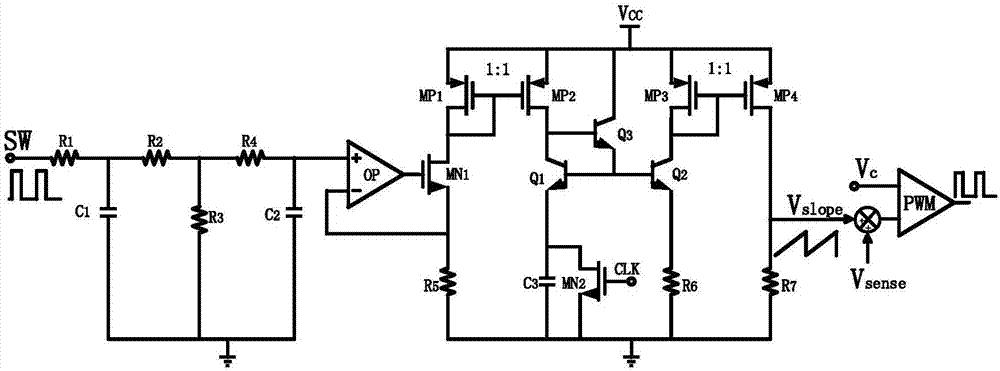
The invention discloses an adaptive slope compensation circuit suitable for controlling a buck converter in a peak current mode, and belongs to the technical field of an electronic circuit. A voltage in a switching node SW of the buck converter is sampled directly, and then filtering in two times is performed to obtain a direct current value, which is proportional to the output voltage V<o> of the buck converter, to be used as a positive input voltage of an operational amplifier; the operational amplifier clamps the negative input end to a voltage which is the same as that of the positive input end, namely, voltage drop on a fifth resistor R5; next, by virtue of a current mirror which consists of a first PMOS transistor MP1 and a second PMOS transistor MP2, the charging current of a third capacitor C3 is proportional to the current which flows through the fifth resistor R5; the voltage drop on a sixth resistor R6 is equal to the voltage of the third capacitor C3; in addition, a current mirror is formed by a third PMOS transistor MP3 and a fourth PMOS transistor MP4, so that the current which flows through a seventh resistor R7 is proportional to the current which flows through the sixth resistor R6; and finally the obtained voltage drop of the seventh resistor R7 is the adaptive slope compensation voltage which is proportional to the output voltage V<o> of the buck converter.

Description

technical field [0001] The invention belongs to the technical field of electronic circuits, and in particular relates to an adaptive slope compensation generating circuit suitable for compensation of a step-down DC-DC converter based on peak current mode control. Background technique [0002] Today, as electronic devices are widely used, the market demand for power management integrated circuits continues to rise, and step-down (Buck) DC-DC converters are widely used in communications, computers, industrial automation and other fields. Traditional step-down DC-DC converters are divided into three control modes: current mode, voltage mode and hysteresis control. Among them, the fixed-frequency PWM technology using peak current mode control is widely used because of its good dynamic performance, wide gain bandwidth, easy compensation and excellent EMI characteristics. [0003] However, when the duty cycle of the peak current mode is greater than 50%, there will be sub-harmoni...

Claims


Application Information

Patent Timeline
IPC IPC(8): H02M3/158
CPCH02M3/158
Inventor 明鑫赵佳祎唐韵扬高笛魏秀凌王卓张波
Owner UNIV OF ELECTRONIC SCI & TECH OF CHINA
Learn More