
Water-cooling system and heat exchange method of Smart Rack integrated cabinet

A water-cooling system and a complete cabinet technology, applied in cooling/ventilation/heating renovation, electrical components, electrical equipment structural parts, etc., can solve problems such as loud noise and insufficient air supply in the machine room, and achieve the effect of enhancing heat exchange efficiency

Inactive Publication Date: 2017-08-29
ZHENGZHOU YUNHAI INFORMATION TECH CO LTD
View PDF3 Cites 1 Cited by
  • Summary
  • Abstract
  • Description
  • Claims
  • Application Information

AI Technical Summary

Problems solved by technology

[0003] The technical task of the present invention is to aim at the above existing problems, to provide a Smart Rack with reasonable design, safe use, which can reduce the air volume required by the server, solve the problem of insufficient air supply in the computer room, reduce the fan speed at the same time, and solve the problem of excessive noise. Cabinet water cooling system

Method used


Image

  • Water-cooling system and heat exchange method of Smart Rack integrated cabinet

Examples


Embodiment 1

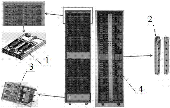
[0022] like figure 1 As shown, the water cooling system of the Smart Rack cabinet of the present invention includes a liquid cooling terminal 1 , a water diversion device 2 , a CDU control unit and a heat exchange unit 3 . The liquid cooling terminal 1 is located at the high power consumption device inside the node of the cabinet 4. The liquid-cooled terminal 1 is formed by connecting liquid-cooled plates through pipelines. The water diversion device 2 is arranged on the back of the cabinet 4 . The CDU control and heat exchange unit 3 is arranged under the cabinet 4, and a height of 4U is reserved at the bottom of the cabinet 4, and the CDU control and heat exchange unit 3 is installed. The water diversion device 2 is connected to the liquid cooling terminal 1, the CDU control and heat exchange unit 3 through blind-mating quick connectors.

Embodiment 2

[0024] In the water-cooled heat exchange method of the Smart Rack complete cabinet of the present invention, the cold medium enters the liquid-cooled terminal 1 from the water inlet of the liquid-cooled terminal 1 along the pipeline, and is carried out by the liquid-cooled plate and the internal high-power consumption device of each U node in the cabinet 4. Heat exchange, transfer the heat to the cold medium, and take it out of the node by the water outlet. The heat medium coming out of each U node is collected by the water diversion device 2 and transported to the heat exchanger of the CDU control and heat exchange unit 3, through which heat exchange occurs with the cold water provided by the external water tower, and the heat exchange occurs through the wall during this process. Without mixing, the heat is transferred to an external water tower and taken out of the engine room. The hot medium turns into cold medium after passing through the heat exchanger, and is evenly retu...


PUM


Abstract

The invention discloses a water-cooling system and exchange method of a Smart Rack integrated cabinet, and belongs to the technical field of heat dissipation of a server. The water-cooling system of the Smart Rack integrated cabinet comprises a liquid-cooling terminal, a water separation and collection device and a central display unit (CDU) control and heat exchange unit, wherein the liquid-cooling terminal is arranged in a node and is formed by connecting liquid-cooling plates by a pipeline, the water separation and collection device communicates with the liquid-cooling terminal and the CDU control and heat exchange unit respectively by rapid connectors and is used for collecting and transmitting a heat medium of the liquid-cooling terminal to the CDU control and heat exchange unit for heat exchange with a heat exchanger in the CDU control and heat exchange unit, and a cold medium after heat exchange is sent to the liquid-cooling terminal. The water-cooling system of the Smart Rack integrated cabinet is reasonable in design, the wind quantity demanded by a server can be reduced, and the problem of insufficient wind supply to a machine room is solved; and meanwhile, the rotational speed of a fan is reduced, the problem of excessive large noise is solved, and the water-cooling system has good promotion and application values.

Description

technical field [0001] The invention relates to the technical field of server heat dissipation, and specifically provides a water cooling system and a heat exchange method for a Smart Rack complete cabinet. Background technique [0002] With the rapid development of society and economy, the application fields of computers are becoming more and more extensive. Compared with traditional computers, servers have better stability, scalability and performance. With the further development of social economy, large-scale enterprises further increase the performance requirements of servers. The improvement of server performance leads to an increase in the heat generated by servers during operation. In order to ensure the normal operation of servers, more efficient heat dissipation methods are required. The current Rack cabinet adopts a single cooling mode for heat dissipation, and fans are used to form a fan wall at the back of the server system to provide the power of the system ai...

Claims


Application Information

Patent Timeline
Patent Type & Authority Applications(China)
IPC IPC(8): H05K7/20
CPCH05K7/20627H05K7/20554
Inventor 李钟勇孙锐羽
Owner ZHENGZHOU YUNHAI INFORMATION TECH CO LTD
Learn More