lighting device
A technology for lighting devices and diffusion areas, applied in lighting devices, components of lighting devices, display devices, etc.
- Summary
- Abstract
- Description
- Claims
- Application Information
AI Technical Summary
Problems solved by technology
Method used
Image
Examples
no. 1 Embodiment approach
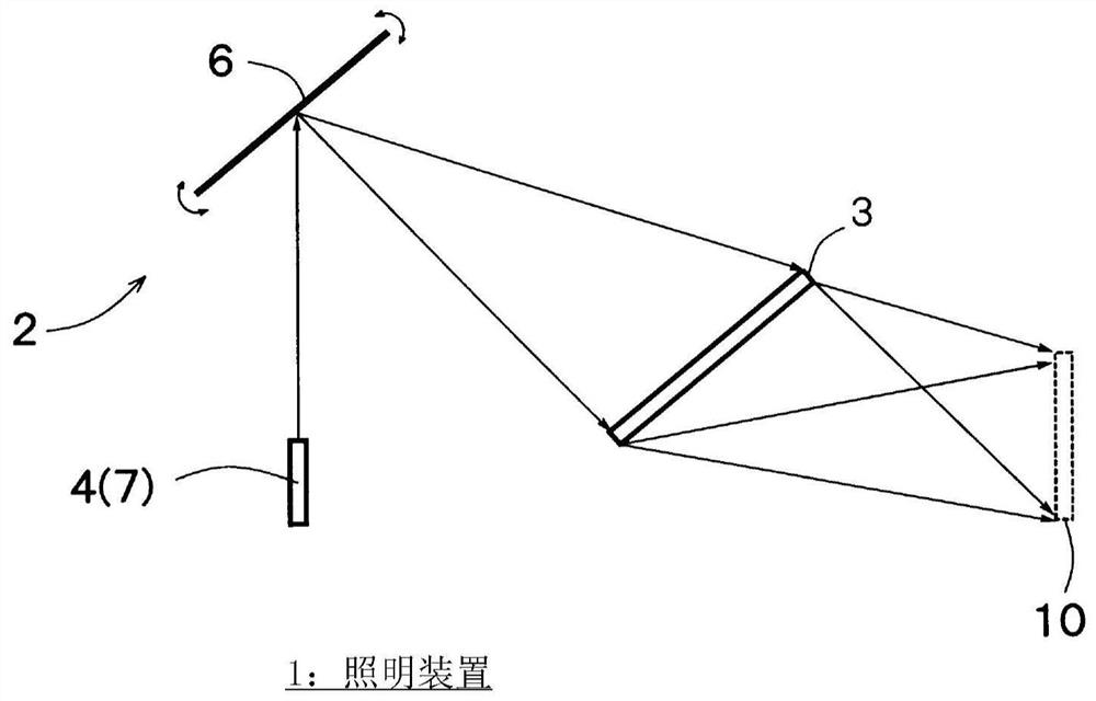
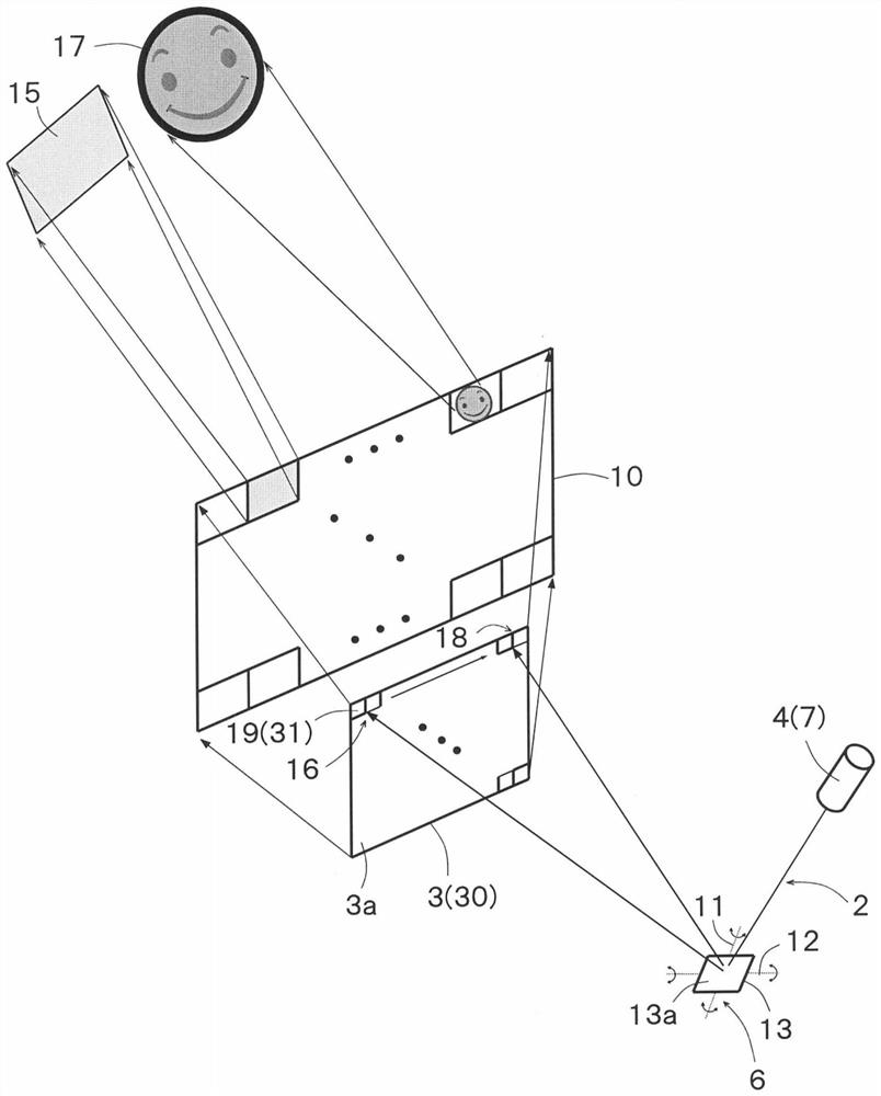
[0199] figure 1 It is a figure which shows the schematic structure of the illuminating device 1 which concerns on 1st Embodiment of this invention. figure 1 The illuminating device 1 includes an illuminating device 2 and an optical element 3. The irradiation device 2 has a laser light source 4 and a scanning unit 6 .
[0200] The laser light source 4 emits coherent light, that is, laser light. The laser light source 4 may be provided with a plurality of light source units having different emission wavelength bands, but may also be configured such that one or more light source units emitting laser light of a single wavelength band are provided. In this embodiment, an example in which one or more light source units that emit laser light in a single wavelength band are provided will be described.
[0201]The scanning unit 6 scans the plurality of laser beams emitted from the laser light source 4 on the optical element 3 . The scanning part 6 can move the laser light source 4 ...
no. 2 Embodiment approach
[0234] In the second embodiment described below, the timing of laser light from the laser light source 4 is controlled.
[0235] Figure 5 It is a figure which shows the schematic structure of the illuminating device 1 of 2nd Embodiment of this invention. Figure 5 The lighting device 1 of the lighting device 2 is provided with a timing control unit 5 inside the lighting device 2 and figure 1 different. also, Figure 5 The laser light source 4 has a plurality of light source units 7 that emit a plurality of coherent lights with different emission wavelength bands, that is, laser light. The plurality of light source units 7 may be provided independently, or may be a light source module in which a plurality of light source units 7 are arranged in a row on a common substrate. The laser light source 4 of the present embodiment only needs to have at least two light source units 7 having different emission wavelength bands, and two or more types of emission wavelength bands are ...
no. 3 Embodiment approach
[0256] In the third embodiment described below, the method of illuminating objects existing in the area to be illuminated 10 is changed.
[0257] Figure 10 is a diagram showing a schematic configuration of an illumination device 1 according to a third embodiment of the present invention, Figure 11 and Figure 12 is shown by Figure 10 A diagram of the lighting range illuminated by the lighting device 1. Figure 10 The lighting fixture 1 except figure 1 In addition to the configuration of the lighting device 1, an object detection unit 21 is further provided. The object detection unit 21 detects an object 22 present within a predetermined range 23 capable of being illuminated by the optical element 3 . That is, the object detection unit 21 detects that there is a Figure 10 The object 22 within the illumination range 23 of the laser illumination of the illuminated area 10 . The object 22 is a person, a vehicle, a living body, etc., and the object may be a moving objec...
PUM
 Abstract
Description
Claims
Application Information
 - R&D
- Intellectual Property
- Life Sciences
- Materials
- Tech Scout
- Unparalleled Data Quality
- Higher Quality Content
- 60% Fewer Hallucinations
Browse by: Latest US Patents, China's latest patents, Technical Efficacy Thesaurus, Application Domain, Technology Topic, Popular Technical Reports.
© 2025 PatSnap. All rights reserved.Legal|Privacy policy|Modern Slavery Act Transparency Statement|Sitemap|About US| Contact US: help@patsnap.com


