
Balloon catheter with marker and processing and positioning methods

A balloon catheter, marking technology, applied in balloon catheter, catheter, medical science, etc., can solve problems such as difficulty in accurately measuring the true diameter of the ring

Inactive Publication Date: 2017-09-01
茵特瓦医疗有限公司
View PDF0 Cites 22 Cited by
  • Summary
  • Abstract
  • Description
  • Claims
  • Application Information

AI Technical Summary

Problems solved by technology

CT measurements of annulus diameter are not performed in real time, and are not performed under stretching conditions such as those found during implantation of TAVR devices; the presence of calcium makes it difficult to accurately measure the true diameter of the annulus

Method used


Image

  • Balloon catheter with marker and processing and positioning methods
  • Balloon catheter with marker and processing and positioning methods
  • Balloon catheter with marker and processing and positioning methods

Examples


Embodiment Construction

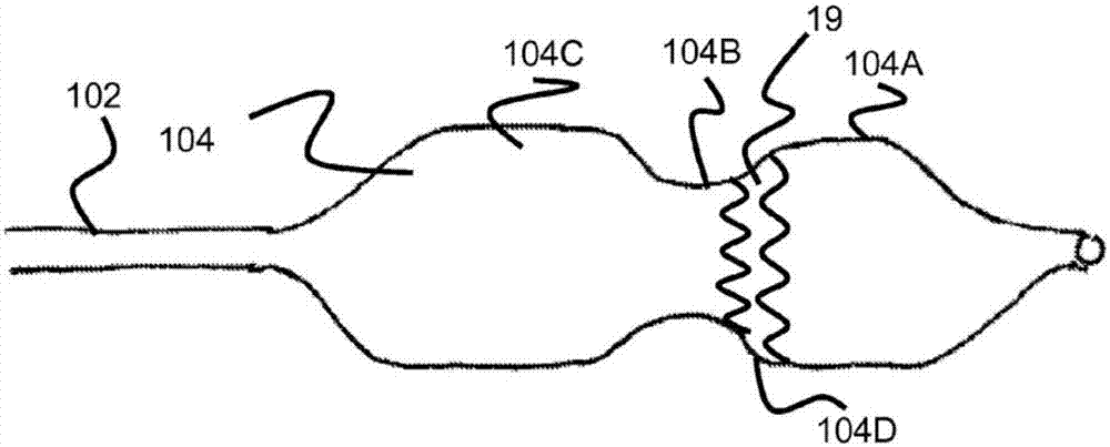
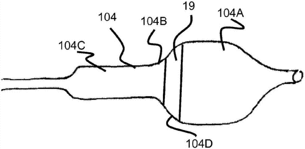
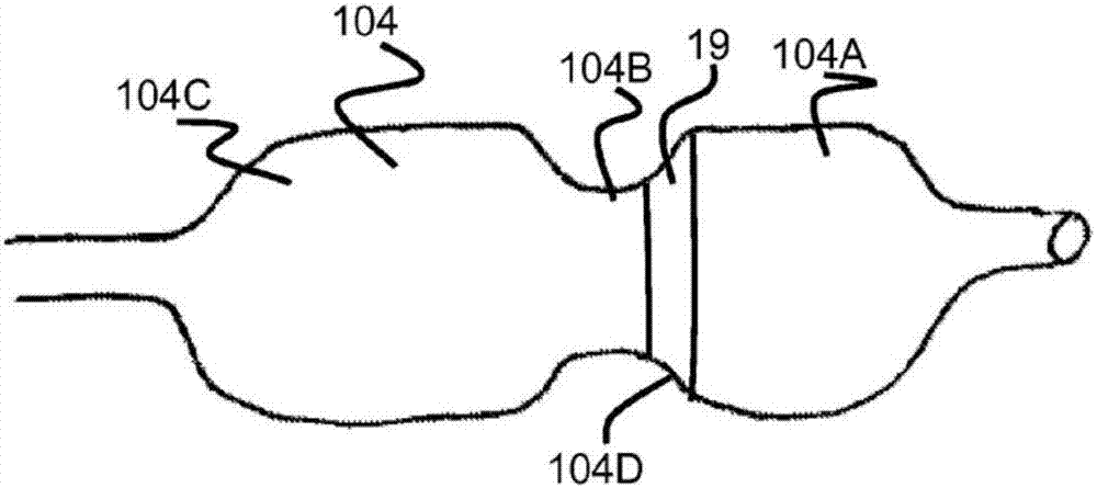
[0063] figure 1 It is shown that the distal end of the balloon catheter in this embodiment has a balloon 104, and its construction material can be nylon, Pebax, PET, polyurethane, and the structure can be woven or unwoven. Such as figure 1 As shown, the balloon 104 includes a proximal end 104C and a distal end 104A and a waist 104B between the proximal end 104C and the distal end 104A. When inflated to a working pressure of 1-4atm, the distal end 104A and proximal end 104C have a diameter of 20-30mm, and the diameter of the waist 104B ranges from 16-25mm; and the diameter of the waist 104B is 2-7mm smaller than the diameter of the proximal and distal ends. In this embodiment, the balloon 104 has a single chamber and uniform pressure throughout the interior.

[0064] The balloon 104 communicates with the catheter 102 through its proximal end 104C, and is used for inflating the fluid so that the working pressure inside the balloon 104 rises and expands. The expandable stent 1...


PUM


Abstract

The invention discloses a balloon catheter with a marker and processing and positioning methods. The balloon catheter comprises a catheter. The near end of the catheter is connected to a fluid conveying device while the far end is provided with a balloon communicating with the fluid conveying device. The balloon comprises the far end, the near end and a waist between the far end and the near end. The maximum diameter of the waist is smaller than the maximum diameter of the far end and the near end. Marker rings are distributed around the balloon. By means of an X-ray or ultrasonic imaging technology, the marker on the balloon catheter can be displayed in real time in an operating process, and the release degree of the balloon catheter and the position relationship with an aortic valve ring are determined by means of position and shape of the marker.

Description

technical field [0001] The invention relates to the field of interventional surgical instruments, in particular to a balloon catheter and a processing and positioning method. Background technique [0002] Balloon catheters for valvuloplasty have been used to post-dilate stented valves placed via transcatheter aortic valve replacement (TAVR). A valvuloplasty balloon catheter is placed within the stented valve and expanded after the TAVR device reaches position across the narrowed native aortic valve. This post-expansion brings the stent-valve stent structure into more direct contact with the surrounding tissue, including the native aortic valve leaflets and the calcium nodules associated with the leaflets, aortic sinus, and left ventricular outflow tract (LVOT), thereby Reduces the amount of blood leakage around the perimeter of the stent-valve. [0003] For self-expanding (SE) TAVR devices, the post-dilation step can ensure that underlying tissues such as native valve leaf...

Claims


Application Information

Patent Timeline
Patent Type & Authority Applications(China)
IPC IPC(8): A61F2/24
CPCA61F2/0077A61F2/2433A61F2210/00A61F2240/001A61F2250/0058A61F2250/0097
Inventor 林浩昇曾敏訾振军雷荣军张志飞
Owner 茵特瓦医疗有限公司
Learn More