Eureka AIR delivers breakthrough ideas for toughest innovation challenges, trusted by R&D personnel around the world.

Injection molding equipment for automobile engine parts

An automobile engine and injection molding technology, which is applied to household components, household appliances, and other household appliances, etc., can solve the problems of troublesome opening of injection molds, low production efficiency, and high cost, so as to improve injection molding efficiency and quickly and conveniently open molds , the effect of simple structure

Pending Publication Date: 2017-09-01
天津华恒汽车部件有限公司
View PDF0 Cites 0 Cited by
  • Summary
  • Abstract
  • Description
  • Claims
  • Application Information

AI Technical Summary

Problems solved by technology

The disadvantage of this method is that after the injection molding is completed, the manipulator first needs to take out the mold core from the fixed mold, place it on the working platform of the next process, and then clamp the mold core that needs to be injected into the fixed mold. Injection molding is time-consuming and labor-intensive, the production efficiency is not high, and the opening of the injection mold is very troublesome, and the traditional injection molding machine needs to close the mold before injecting, and then drive the injection head to the position corresponding to the sprue of the mold, and finally give an injection
The movement of the injection head is separate from the mold closing process, and needs to be driven separately by different power sources. The position of the movable template and the fixed template is accurate during molding, and the position of the movable template and the fixed template is prone to shift after multiple injection molding

Method used


Image

  • Injection molding equipment for automobile engine parts
  • Injection molding equipment for automobile engine parts

Examples


Embodiment Construction

[0023] The technical solutions of the present invention will be clearly and completely described below in conjunction with the accompanying drawings. Apparently, the described embodiments are some of the embodiments of the present invention, but not all of them. Based on the embodiments of the present invention, all other embodiments obtained by persons of ordinary skill in the art without making creative efforts belong to the protection scope of the present invention.

[0024] In the description of the present invention, it should be noted that the terms "center", "upper", "lower", "left", "right", "vertical", "horizontal", "inner", "outer" etc. The indicated orientation or positional relationship is based on the orientation or positional relationship shown in the drawings, and is only for the convenience of describing the present invention and simplifying the description, rather than indicating or implying that the referred device or element must have a specific orientation, ...


PUM


Abstract

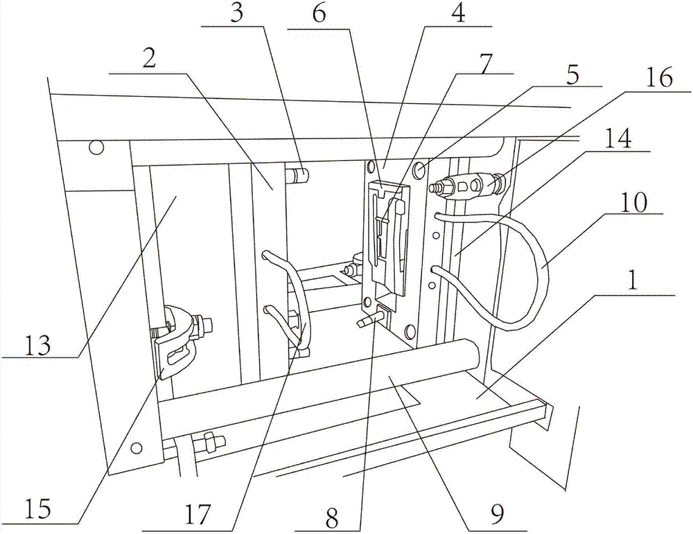
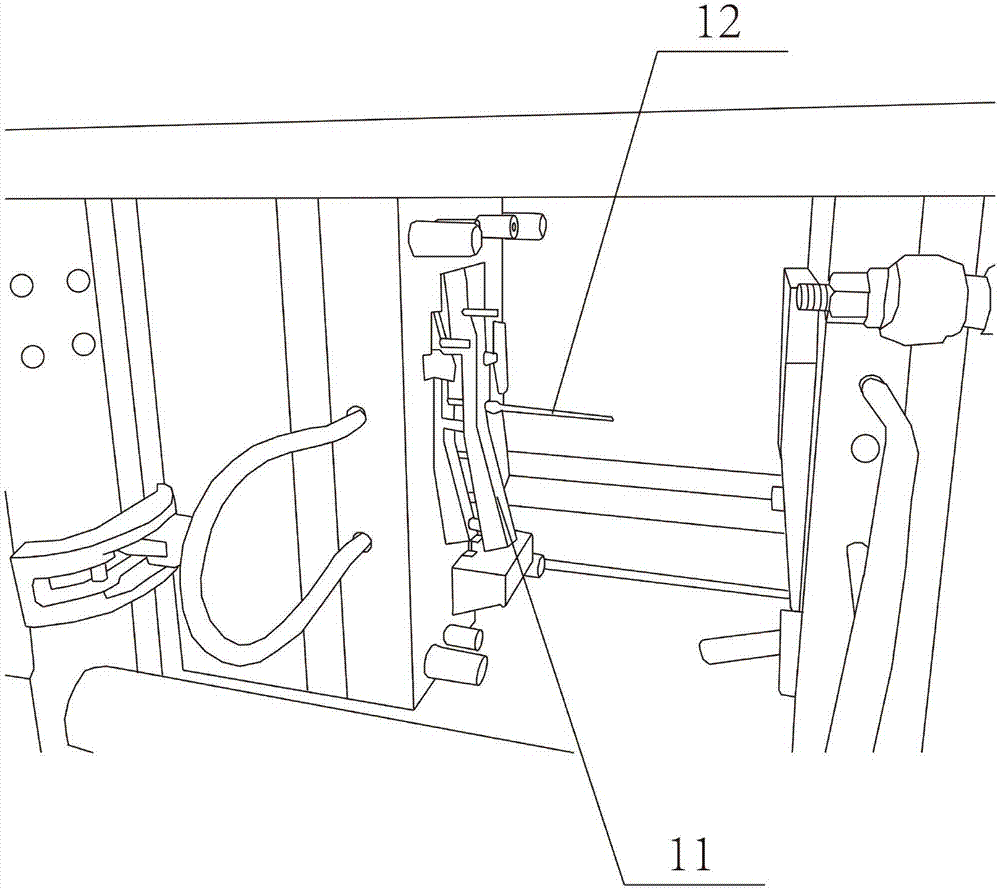
The invention aims to provide injection molding equipment for automobile engine parts. The equipment comprises a rack, a moving mould plate, a guiding column, a fixed mould plate, a wholly-moving oil cylinder, a first oil pipe, a moving mould core, a first driving device, a second driving device and a first oil path control device. The equipment is characterized in that the first driving device and the second driving device are arranged on the rack; the moving mould plate is arranged on one side of the first driving device; the first driving device is mutually connected with the moving mould plate; and the fixed mould plate is arranged on one side of the second driving device. According to the injection molding equipment disclosed by the invention, the wholly-moving oil cylinder is arranged between the moving mould plate and the fixed mould plate; the wholly-moving oil cylinder can output larger and stable propulsive force by inputting the first oil pipe and the second oil pipe, so that stable contact force between the moving mould plate and the fixed mould plate can be achieved, and the equipment is driven by a wholly-moving press cylinder in an injection molding process, so that the structure is simple, the use is convenient and the cost is lower.

Description

technical field [0001] The invention relates to injection molding equipment, in particular to an injection molding equipment for automobile engine parts. Background technique [0002] At present, automobile engine parts play an important role in the automobile assembly and production process, and are the basis for the safe and stable operation of the engine. Injection molding of automotive engine parts is also gaining in importance as a step in the automotive zero-price process. Automobile engine parts are generally suitable for thermoplastic thermoforming. Utilizing the hot-melt principle of thermoplastics, the molten plastic is injected into the cavity of the mold through the injection molding machine, then cooled and shaped, and the mold is opened to take out the plastic product. Injection molding requires The fixed mold and the movable mold, the current method is to put the two mold cores with the concave ends facing each other, connect the two mold cores to form a grou...

Claims


Application Information

Patent Timeline
Patent Type & Authority Applications(China)
IPC IPC(8): B29C45/67B29C33/76B29C45/82
CPCB29C33/76B29C45/67B29C45/82B29L2031/749
Inventor 董学震
Owner 天津华恒汽车部件有限公司
Why Eureka
Eureka Blog
Learn More