Acoustic emission positioning method of underground gas pipeline leakage point based on Beidou positioning
A technology of gas pipeline and positioning method, which is applied in the direction of pipeline system, gas/liquid distribution and storage, mechanical equipment, etc., can solve the problems of road traffic and safety impact, waste of resources, etc., achieve high positioning accuracy, small ground damage, and avoid The effect of wasting resources
- Summary
- Abstract
- Description
- Claims
- Application Information
AI Technical Summary
Problems solved by technology
Method used
Image

Examples
Embodiment Construction
[0045] The acoustic emission positioning method of the leakage point of the buried gas pipeline based on Beidou positioning according to the present invention will be explained and described in detail below in conjunction with the drawings of the description.
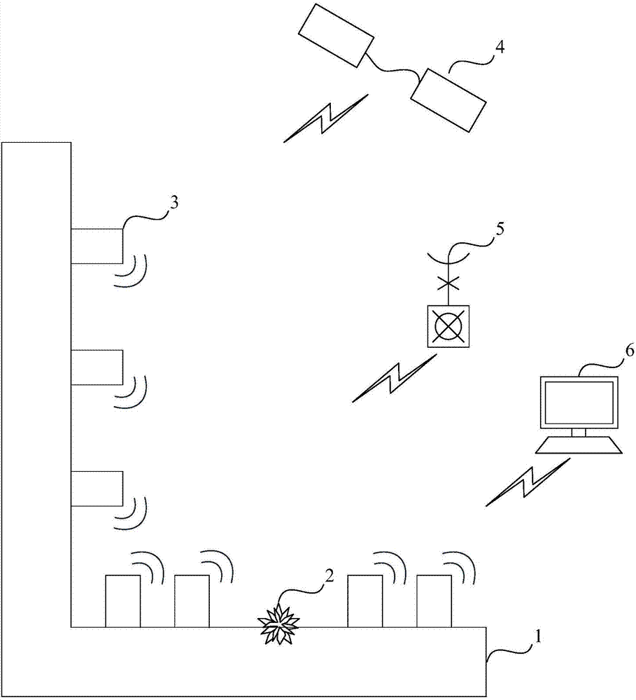
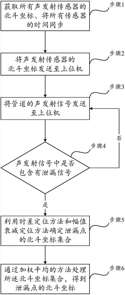
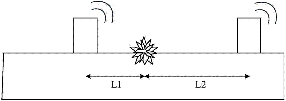
[0046] Such as Figure 1-5 As stated above, the present invention discloses an acoustic emission positioning method for the leakage point of buried gas pipelines based on Beidou positioning. The present invention calculates the location of the leakage point based on the Beidou positioning system through time difference positioning, amplitude attenuation positioning and weighted average, so that The present invention solves the problems of difficulty in locating leakage points and inability to detect leakage of small-flow buried gas pipelines in the prior art. The acoustic emission positioning method includes the following steps, such as figure 1 , 2 shown.
[0047]Step 1, the acoustic emission sensor 3 integrated wit...
PUM
 Abstract
Description
Claims
Application Information